Crimping Pliers Die and Crimping Pliers

a technology of crimping pliers and pliers, which is applied in the direction of manufacturing tools, electrical equipment, line/current collector details, etc., can solve the problem that the type of die does not generate a continuous pressing of the workpi

Active Publication Date: 2021-10-28
WEZAG GMBH & CO KG
View PDF3 Cites 4 Cited by
  • Summary
  • Abstract
  • Description
  • Claims
  • Application Information

AI Technical Summary

Benefits of technology

[0027]It is possible that the rotational position of the stop body is secured by friction or in any other way. For one embodiment of the crimping pliers die a stop body latching device or stop body locking device is provided. The stop body latching device or stop body locking device latches or locks the stop body in predefined stop body rotational angles of the stop body relative to the die half so that it is possible to secure the operational position of the stop body.
[0028]There are a lot of options for the design of the stop body latching device or stop body locking device. For one proposal of the invention, the stop body and the die half each comprise stop body guiding surfaces. The stop body guiding surfaces have an orientation vertical to the stop body rotational axis. During the rotation about the stop body rotational axis, the stop body and the die half are guided relatively to each other on the stop body guiding surfaces. In this case one stop body guiding surface comprises a recess. A stop body latching element or stop body locking element biased by a spring is arranged in this recess. The other stop body guiding surface comprises a plurality of stop body latching recesses or stop body locking recesses. For providing the latching or locking effect, in the predefined relative stop body rotational angles wherein an insertion stop associated with the stop body rotational angle is arranged at the desired position relative to the die accommodation the stop body latching element or stop body locking element is at least partially arranged in the stop body latching recess or stop body locking recess. In this way it is possible to secure an operating position of the stop body set by the user.

Problems solved by technology

Accordingly, this type of dies does not generate a continuous pressing of the workpiece between the die halves over a large surface area.

Method used


Image

  • Crimping Pliers Die and Crimping Pliers
  • Crimping Pliers Die and Crimping Pliers
  • Crimping Pliers Die and Crimping Pliers

Examples


Embodiment Construction

[0056]In the present description of the figures partly the same reference number is used for components which are identical or similar with respect to their geometry and / or function. In this case the components are distinguished from each other by an additional letter a, b, . . . . In this case, reference is made to these components with or without the additional letter which then relates to one single component, a plurality of these components or all of these components.

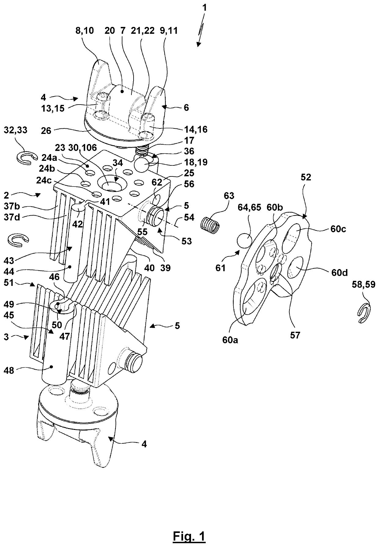
[0057]FIG. 1 shows in a three-dimensional exploded view a crimping pliers die 1. The crimping pliers die 1 comprises an upper die half unit 2 and a lower die half unit 3. The upper die half unit 2 and the lower die half unit 3 have identical designs so that for the following description primarily reference is made to the die half unit 2 (the corresponding then also applies for the other die half unit 3).

[0058]The die half unit 2 comprises a holding body 4 and a die half 5.

[0059]The holding body comprises a bearing p...


PUM


Abstract

The invention relates to a crimping pliers die (1) comprising two die half units (2, 3). The die half units (2, 3) are guided by a guide (51) relatively to each other over the crimping stroke. Crimping surfaces (40, 41) of the die halves (5) are formed by front surfaces of engaging ribs (37). The guide (51) comprises a guiding rod (43) formed by an end-sided thickening (42) of a rib (37) and/or the guide (51) comprises a guiding recess (50) formed by a guiding recess section (45) which connects two ribs (37) to each other. The crimping pliers die (1) can be used for crimping pliers which can e. g. be used for crimping wire end sleeves.

Description

CROSS REFERENCE TO RELATED APPLICATIONS[0001]This application claims priority to co-pending German Patent Application No. 10 2020 111 522.9 filed Apr. 28, 2020.FIELD OF THE INVENTION[0002]The present invention relates to a crimping pliers die designated for being used in crimping pliers. The crimping pliers die comprises two die half units. Crimping surfaces of the die half units delimit a die accommodation. A workpiece can be introduced into the die accommodation. The workpiece can then be crimped between the crimping surfaces of the die half units. The crimping pliers die is e.g. used for pressing a workpiece which is embodied as a wire end sleeve (with or without an isolation collar) with a cable arranged therein. Furthermore, the invention relates to crimping pliers with a crimping pliers die of this type.BACKGROUND OF THE INVENTION[0003]The publication EP 0 516 598 B1 discloses a crimping pliers die comprising two die half units. The die half units are each supported for being ...

Claims


Application Information

Patent Timeline
Patent Type & Authority Applications(United States)
IPC IPC(8): H01R43/042
CPCH01R43/042B25B27/146
Inventor GLOCKSEISEN, THOMASZINSER, ROMAN
Owner WEZAG GMBH & CO KG
Why Eureka
Try Eureka