Embolism device and spring coils thereof

a technology of embolism device and coil, which is applied in the field of medical instruments, can solve the problems of difficult to achieve stable basket formation and compliant packing of coils, unsuitable coils for the embolization of different aneurysms of various shapes and sizes, and severe threats to our health, and achieves high deflectibility and compressive properties. , the effect of high resistance to compression

Pending Publication Date: 2021-11-04
MICROPORT NEUROTECH SHANGHAI
View PDF0 Cites 0 Cited by
  • Summary
  • Abstract
  • Description
  • Claims
  • Application Information

AI Technical Summary

Benefits of technology

[0005]In view of this, the present invention provides an embolization device and a coil thereof with both sufficient stability and satisfactory compliance, which can adapt to aneurysms of different shapes and sizes and allow stable, compliant, dense embolization thereof.
[0023]In the proposed embolization device and coil thereof, the coil is formed by joining together at least four structural elements arranged in different planes, which include at least two C-shaped elements and at least one O-shaped or α-shaped element. The at least two C-shaped elements are arranged in two adjacent planes and sequentially joined together to form an S-shaped structure. The three-dimensional S-shaped structure is highly deflectable and compressive, making the coil easy to change its shape to adapt to different aneurysm shapes. Moreover, the Ω- and O-shaped elements are highly resistant to compression and can provide strong support and ensure sufficient stability of the coil. With the advantages of both types of structural elements, the coil has both good stability and good compliance. Therefore, it can adapt to aneurysms of different shapes and sizes, and enables stable, compliant, dense embolization.
[0024]Further, the two adjacent planes where the S-shaped structure is arranged preferably form an angle of 60°-120°, with 90° more preferred. This can result in an additional increase in spatial deflectability of the S-shaped structure and hence in compliance of the coil.
[0025]Furthermore, the embolization device may include a plurality of coils, for example, 2-10 coils, in which any adjacent two can be swiveled with respect to each other about the axis of the embolization device. This imparts higher stability to the embolization device, thereby resulting in an even better aneurysm embolization effect.

Problems solved by technology

Brain aneurysms, also known as intracranial aneurysms, are a severe threat to our health.
However, the three-dimensional structures of existing coils have a significant drawback that it is difficult for them to achieve both stable basket formation and compliant packing.
For example, their constituent elements are simple figure-eight shaped, O-shaped or Ω-shaped coils, which are difficult to compress and poorly compliant, making the coils unsuitable for the embolization of different aneurysms of various shapes and sizes.

Method used


Image

  • Embolism device and spring coils thereof
  • Embolism device and spring coils thereof
  • Embolism device and spring coils thereof

Examples


embodiment 1

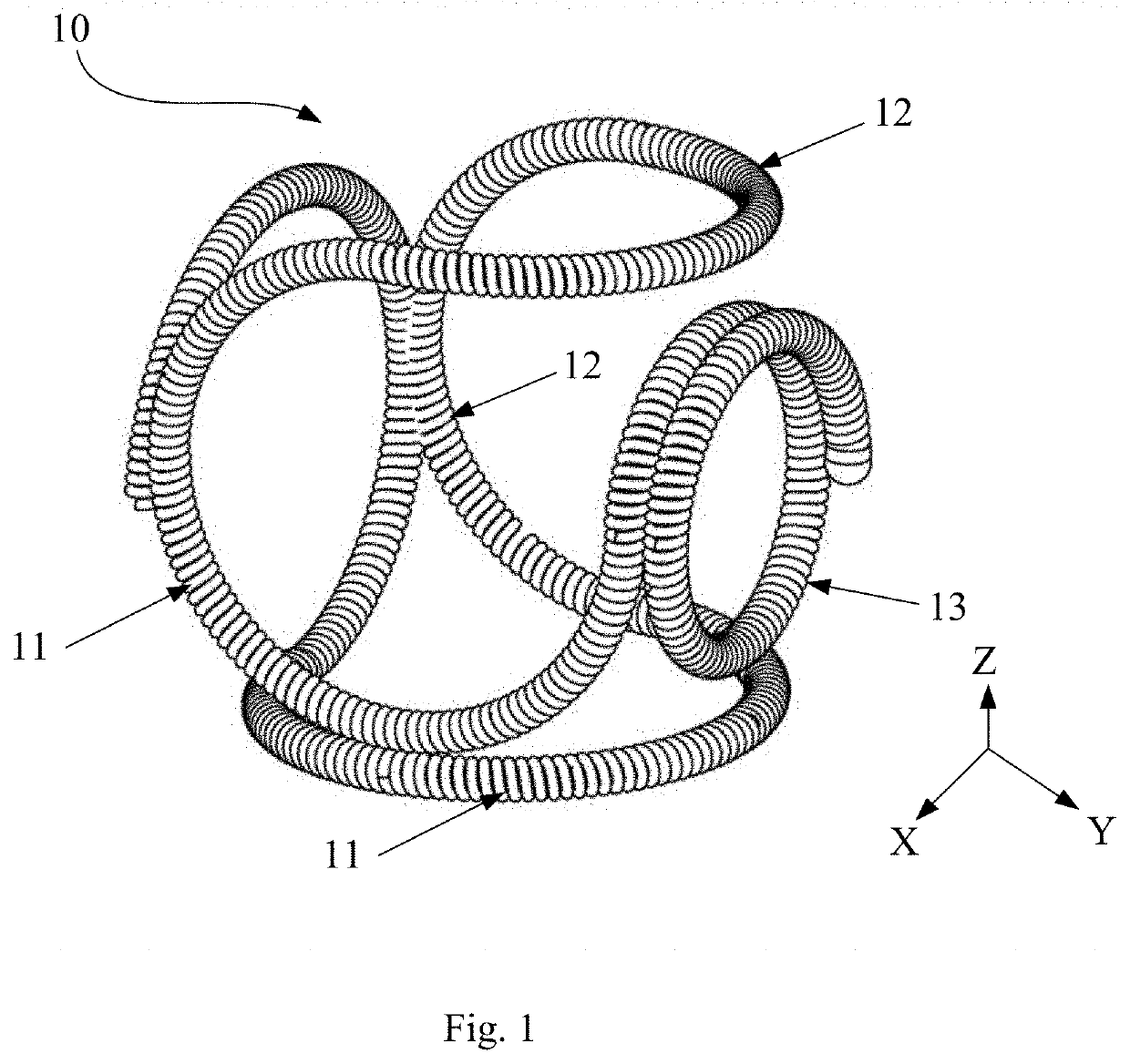
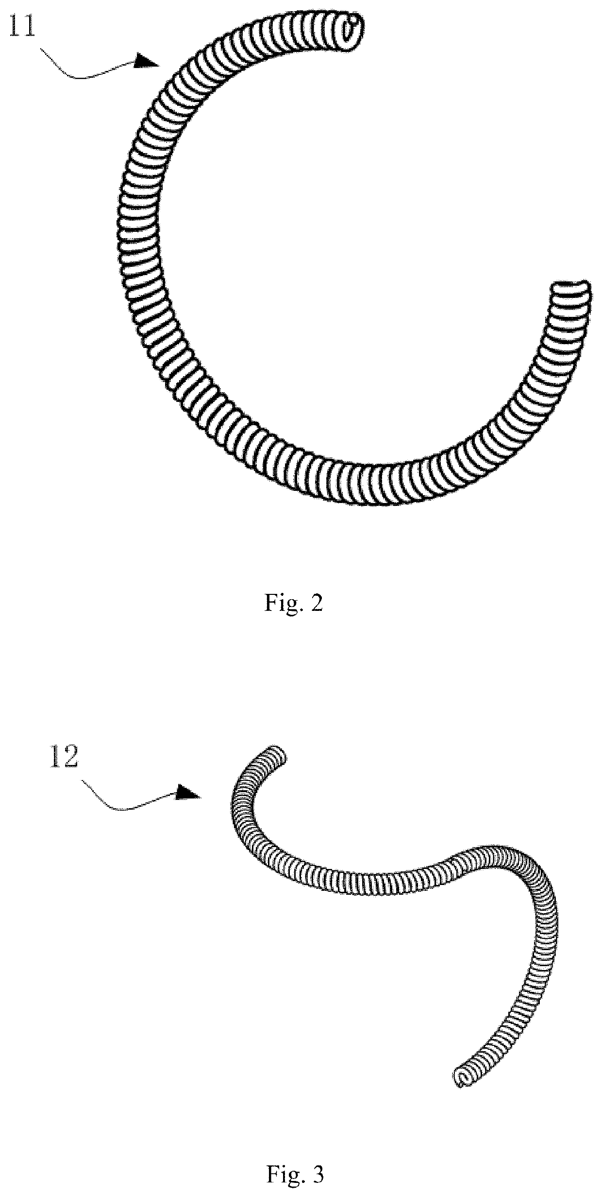
[0043]As shown in FIGS. 1 to 3, a coil 10 according to this embodiment is formed by joining together structural elements, which are of three types and arranged in six planes. The structural elements include O-, Ω- and C-shaped elements 13, 11, 12. There is one O-shaped element 13 and at least two C-shaped elements 12, and the total number of the O-, Ω- and C-shaped elements 13, 11, 12 is six. The six structural elements are arranged in the respective six planes so that the coil 10 generally appears as a hexahedron. Examples of the hexahedron are not limited to regular hexahedrons, parallel hexahedrons and irregular hexahedrons. In other embodiments, the six structural elements may also be arranged in respective six planes of a polyhedron having at least seven planes, such as an octahedron.

[0044]The O-, Ω- and C-shaped elements 13, 11, 12 may be arranged in many ways, as long as they satisfy several requirements including: preferred arrangement of the O-shaped element 13 at the furth...

embodiment 2

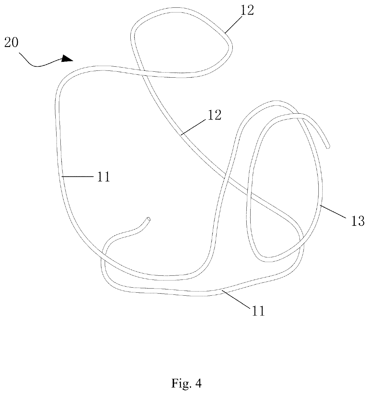
[0051]As shown in FIG. 4, a coil 20 according to this embodiment is formed by joining together structural elements, which are of three types and arranged in five planes. Similarly, the structural elements include O-, Ω- and C-shaped elements 13, 11, 12. There is one O-shaped element 13 and at least two C-shaped elements 12, and the total number of the O-, Ω- and C-shaped elements 13, 11, 12 is five. The five structural elements are arranged in the respective five planes to achieve a coil 20 with a pentahedron structure. Herein, the coil 20 appears as a pentahedron. In other embodiments, the five structural elements may also be arranged in respective five planes of a polyhedron having at least six planes, such as a hexahedron.

[0052]In the pentahedron, the O-, Ω- and C-shaped elements 13, 11, 12 may also be arranged in many ways, and the arrangement may follow substantially the same requirements as Embodiment 1. A further detailed description of how they are arranged with be set forth...

embodiment 3

[0056]A coil 30 according to this embodiment is formed by joining together structural elements, which are of three types and arranged in eight planes Similarly, the structural elements include O-, Ω- and C-shaped elements 13, 11, 12. There is one O-shaped element 13 and at least two C-shaped elements 12, and the total number of the O-, Ω- and C-shaped elements 13, 11, 12 is eight. The eight structural elements are arranged in the respective eight planes to achieve a coil 30 of an octahedron structure. Herein, the coil 30 generally appears as an octahedron. The octahedron is not limited to a regular octahedron, as long as the structural elements are arranged in respective eight planes of a polyhedron.

[0057]In the octahedron, the O-, Ω- and C-shaped elements 13, 11, 12 may also be arranged in many ways, and the arrangement may follow substantially the same requirements as Embodiment 1. A further detailed description of how they are arranged with be set forth below.

[0058]In a preferred...


PUM


Abstract

An embolization device and a coil thereof (10, 20, 30) are disclosed. The coil (10, 20, 30) is formed by joining together at least four structural elements arranged in different planes, which include at least two C-shaped elements (12) and at least one O-shaped element (13) or Ω-shaped (11) element. The at least two C-shaped elements (12) are arranged in two adjacent planes and are sequentially joined together to form an S-shaped structure. The embolization device preferably includes plurality of coils (10, 20, 30) which are joined together side-by-side and end-to-end, wherein in any adjacent two coils (10, 20, 30), one is swivelable about an axis of the embolization device with respect to the other. The Ω-shaped element is structurally stable, allowing the coil (10, 20, 30) to maintain good structural stability. At the same time, the three-dimensional S-shaped structure has good deflectability, which imparts high compliance to the coil (10, 20, 30). With this construction, the coil (10, 20, 30) can satisfy the requirements of both stable basket formation and compliant packing and can adapt to various aneurysms of different shapes and sizes with a dense packing effect.

Description

TECHNICAL FIELD[0001]The present invention relates to the field of medical instruments and, in particular, an embolization device and a coil thereof for use in the treatment of intracranial aneurysms.BACKGROUND[0002]Brain aneurysms, also known as intracranial aneurysms, are a severe threat to our health. With the development of imaging technology and biomaterials for intravascular use, intravascular intervention has replaced surgical clipping as the first choice therapy for intracranial aneurysms thanks to its lower risk and less trauma.[0003]Presently, the treatment of an aneurysm is usually accomplished with a coil. During embolization of the aneurysm, a corresponding shape is formed in the aneurysm by a predetermined shape of the coil, thereby achieving a desired embolization effect. For such treatment, the initial packing density of the coil is one important factor that determines long-term stability of the embolization effect, and a greater coil packing density can result in be...

Claims


Application Information

Patent Timeline
Patent Type & Authority Applications(United States)
IPC IPC(8): A61B17/12
CPCA61B17/12145A61B17/12113A61B2017/00526A61B17/12031A61L31/022A61L31/04A61L2430/36
Inventor GUO, YUANYIPENG, YUNFEIYU, PENGZHA, XUCHEN, BINGWANG, YIQUN BRUCE
Owner MICROPORT NEUROTECH SHANGHAI
Why Eureka
Try Eureka