
Cable crimp cap apparatus and method

a crimping cap and cable technology, applied in the field of medical implants, can solve the problems of sharpness, irritation, and irritation of the crimping end, and achieve the effects of reducing the risk of fracture, reducing the service life, and improving the service li

Pending Publication Date: 2021-11-04
LITTLE ENGINE LLC
View PDF0 Cites 0 Cited by
  • Summary
  • Abstract
  • Description
  • Claims
  • Application Information

AI Technical Summary

Benefits of technology

The crimp cap helps keep cable ends safe and protected, which is helpful in preventing damage to soft tissue.

Problems solved by technology

One problem with prior art sleeves is that they can leave a leave a sharp and / or protruding end after crimping and cable cutting, resulting in a crimped end that can create soft tissue irritation.
The sharpness and irritating features of the prior art devices include both the crimp edge and the frayed end of the cable itself.

Method used


Image

  • Cable crimp cap apparatus and method
  • Cable crimp cap apparatus and method
  • Cable crimp cap apparatus and method

Examples


Embodiment Construction

[0040]In general, the technology described herein provides a cap and crimp system and method that enables provisional and permanently stable tensioning of a tensile member while shielding the cut end of the tensile member.

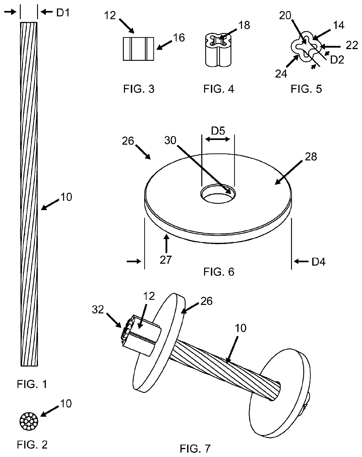
[0041]The anchor, installation system, and installation method described herein are suitable for receiving and securing a tensile member to bone. The term “tensile member” as used herein generally refers to any flexible element capable of transmitting a tensile force, such as a filament, thread, or cable. Nonlimiting examples of known types of tensile members include sutures and orthopedic cables. FIGS. 1 and 2 illustrate a short segment of a representative tensile member 10 having an outside diameter “D1”. Commercially-available tensile members intended to be implanted in the human body may have a diameter “D1” ranging from tens of microns in diameter to multiple millimeters in diameter. Commercially-available tensile members may be made from a variety of material...


PUM


Abstract

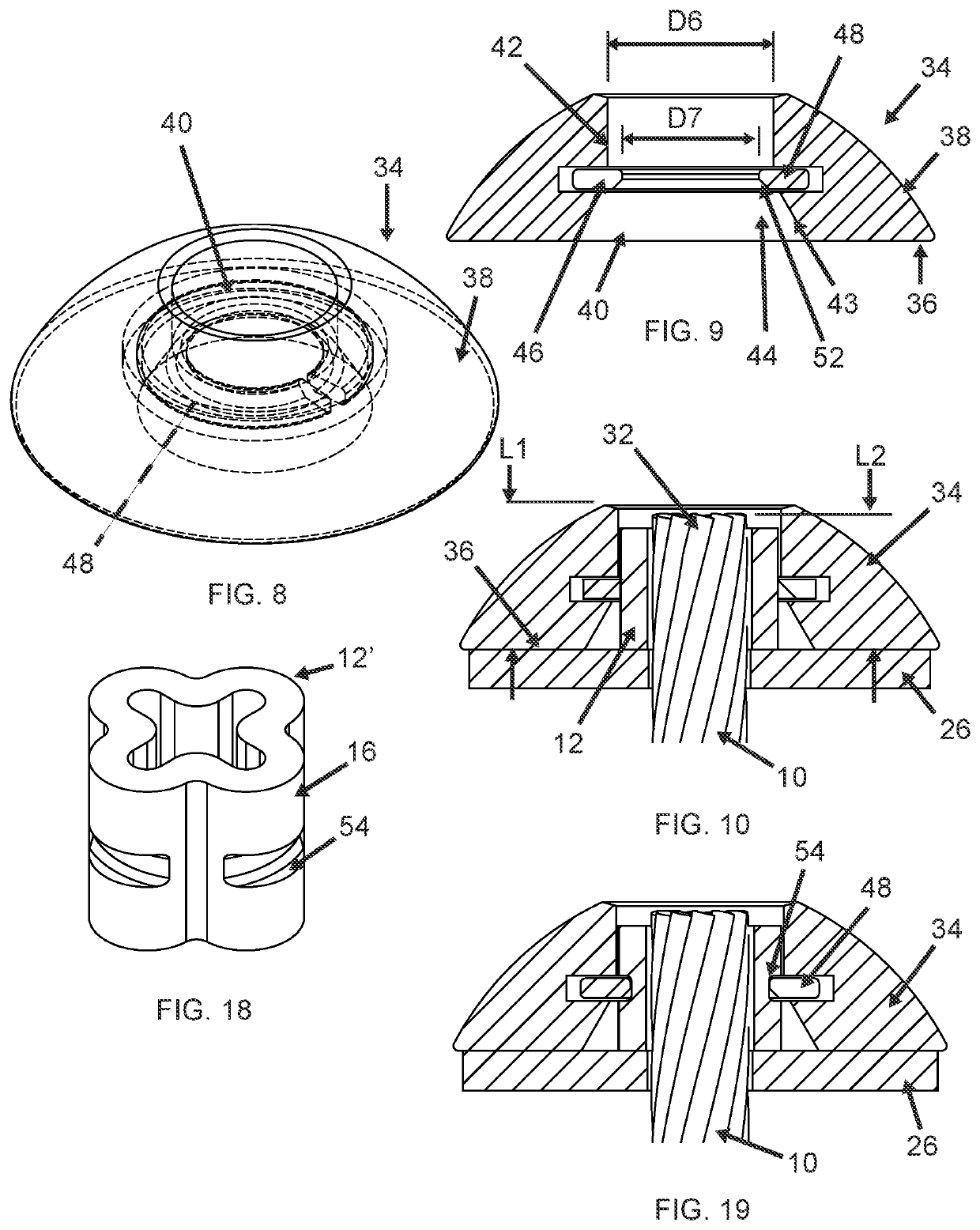
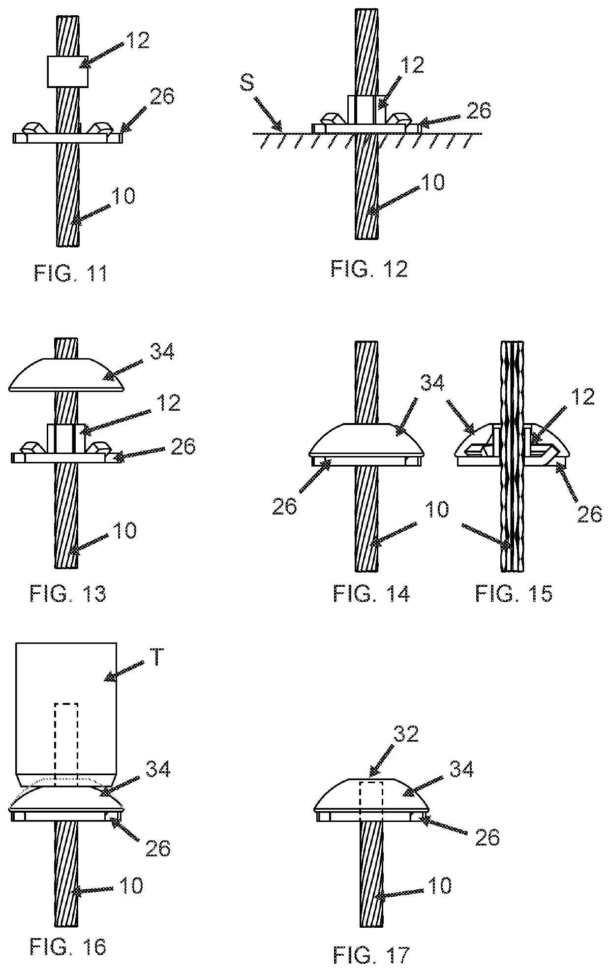
A crimp cap apparatus includes: a crimp sleeve having a peripheral wall defining an exterior surface and an interior passage sized to receive a tensile member having a predetermined outer diameter, the crimp sleeve being configured such that it can be crimped around the tensile member by an application of mechanical force which reduces its dimensions from a first size to a second, smaller size; and a cap having a bottom surface, a convex top surface, a central bore extending from the bottom surface to the top surface for receiving the crimp sleeve, wherein the cap includes a clamping structure disposed in the central bore and configured to permit elastic deflection in response to being pressed over the crimp sleeve the crimp sleeve and apply a clamping force there-to to secure the cap in place.

Description

BACKGROUND OF THE INVENTION[0001]This invention relates generally to medical implants, and more particularly to apparatus used to apply tension along or across a ligament to repair, augment, or replace it, or applying tension across a bone fracture to reduce it.[0002]Medical implants for tensioning purposes typically comprise one or more tensile members (e.g., sutures or orthopedic cables) connected to one or more anchors (e.g., suture anchors or suture locks) to create a converging tensile force between the two anchors. This general concept has been used in the orthopedic and sports medicine fields to repair torn or damaged tendons and ligaments, to replace missing or displaced tendons and ligaments, and to anchor grafted or artificial tendons and ligaments to bones so that they can grow back together.[0003]One particular type of tensile member anchor includes a crimp sleeve which is crimped around a distal end of a tensile member to secure it in place. One problem with prior art s...

Claims


Application Information

Patent Timeline
IPC IPC(8): A61B17/88A61B17/04A61B17/84
CPCA61B17/8869A61B2017/00477A61B17/842A61B17/0487A61B17/82A61B17/8695A61B17/683
Inventor COLE, J. DEANKELLAR, FRANZ W.BISSETTE, MICHAEL D.
Owner LITTLE ENGINE LLC
Learn More