
Control Drone Lighting Device

a technology of drone lighting and control device, which is applied in the field of control drone lighting device, can solve the problems of not supporting drones in inventions, no one of today's manufactures or users has used a combination of spot lights and auxiliary batteries on drones at night for working or playing, and achieve the effect of maintaining power to the dron

Inactive Publication Date: 2021-11-04
BYRD TERESA ELAINE
View PDF0 Cites 5 Cited by
  • Summary
  • Abstract
  • Description
  • Claims
  • Application Information

AI Technical Summary

Benefits of technology

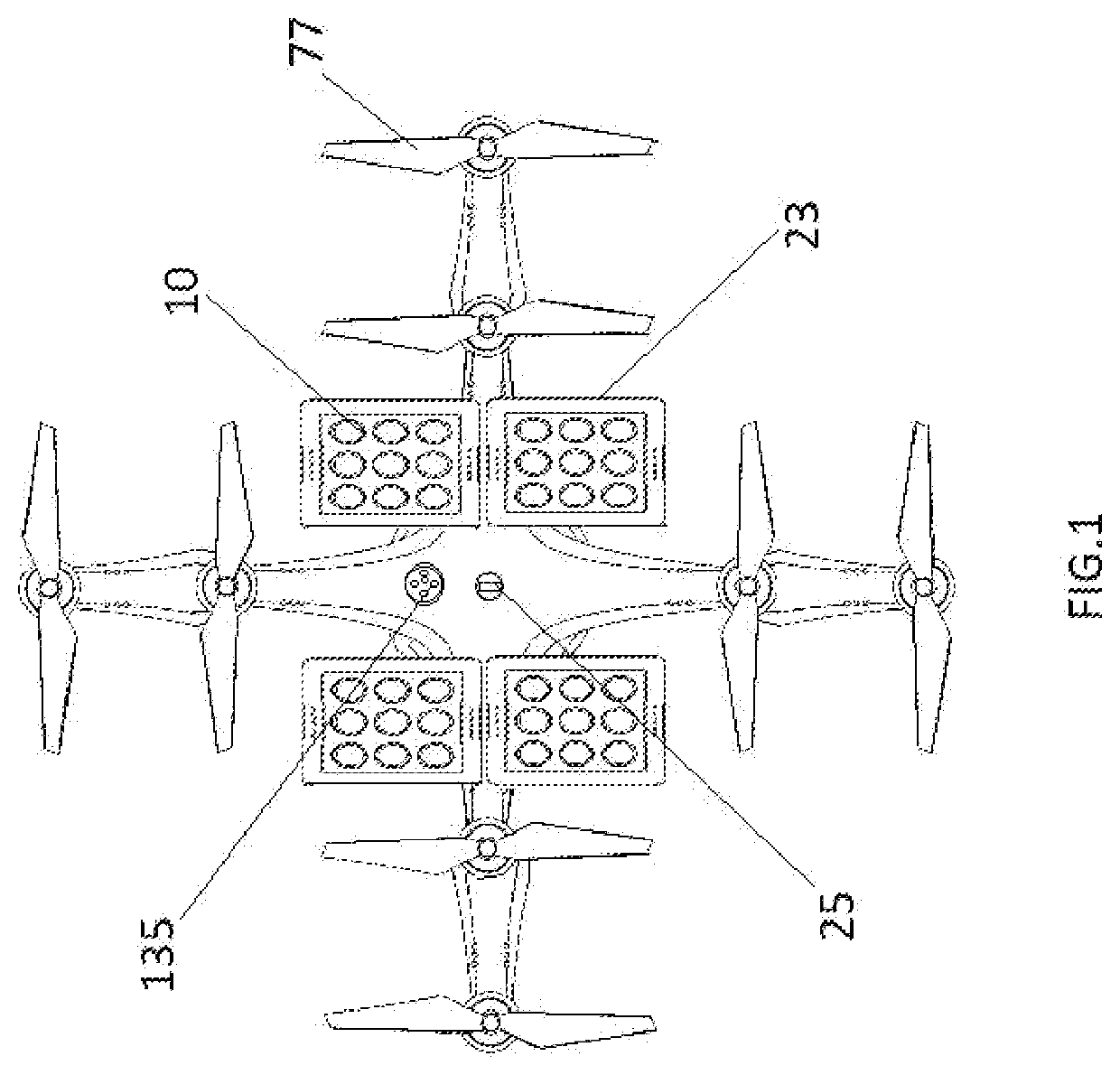
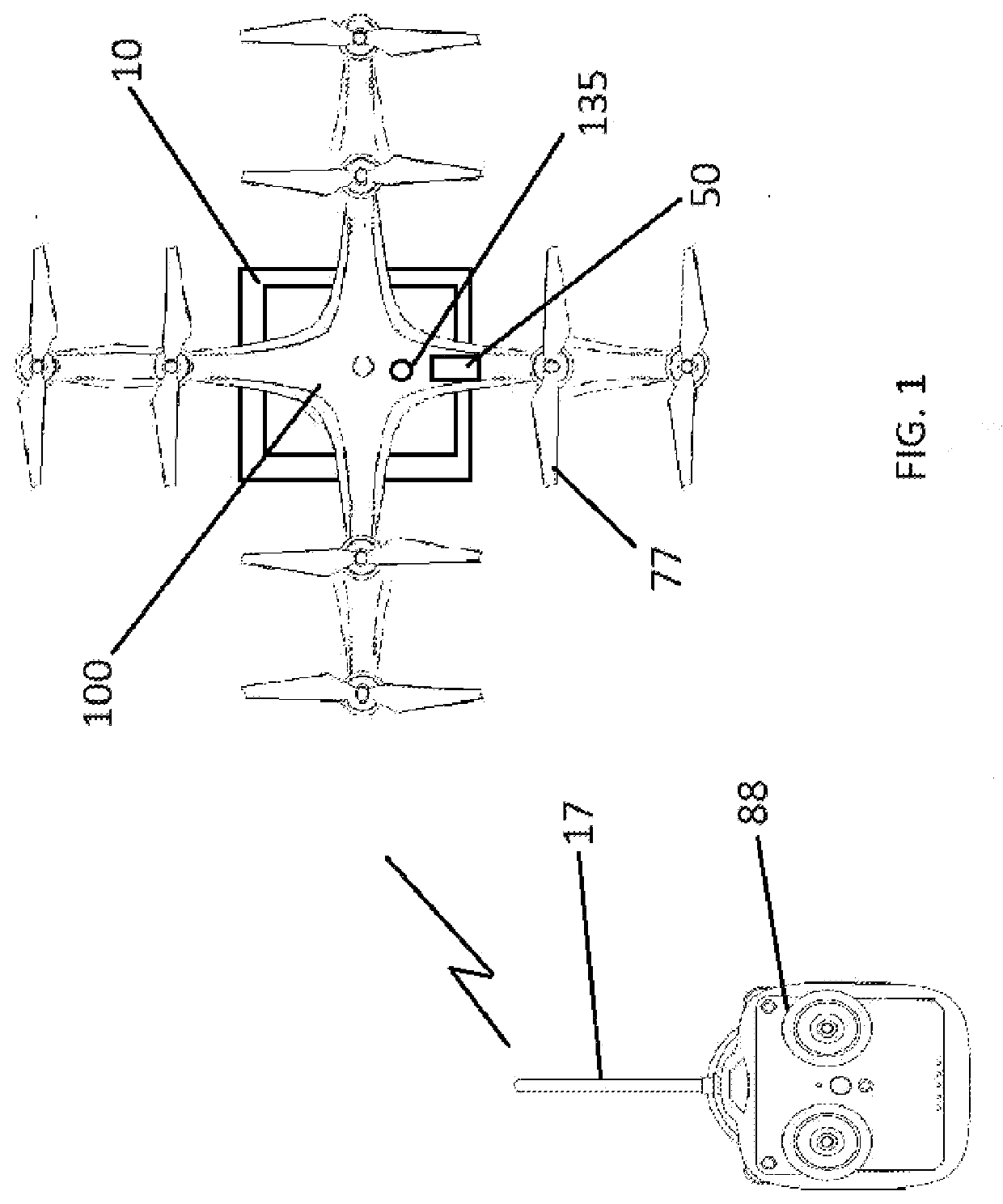
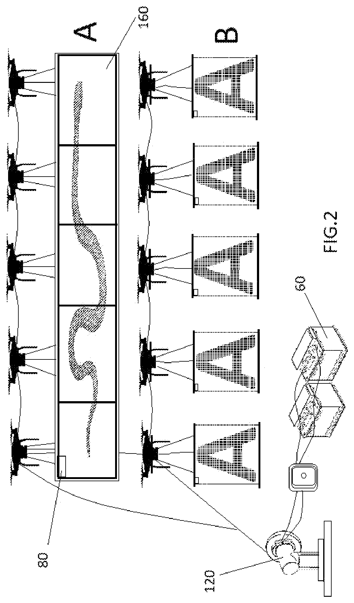
The patent describes a drone that is controlled remotely and powered by a battery or generator. The drone has LED spotlights that are powered by an auxiliary battery or generator that is tethered to the drone. The LED spotlights move independently with the drone, creating a brush of light. The drone also has an additional flight controller, such as a smartphone or tablet, that can control the flight and position of the drone. The patent also describes a voltage reducer that helps reduce the voltage of the drone's components and motor. The LED spotlights can be controlled through the drone's flight controller or an external device like a smartphone.

Problems solved by technology

The prior inventions don't support drones with auxiliary batteries that's under a continuous charging or having a generator for powering there drone, or any other devices such as the use of a bright lighting system for a work area at night or lighting system for playing sport at night in a remote area, that doesn't have electrical power lighting such as a light poles, or any kind lighting sources for a nighttime work or play event; however, none of today's manufacture or in users has used a combination of auxiliary batteries and a spot lights on a drones at night for working or play.

Method used


Image

  • Control Drone Lighting Device
  • Control Drone Lighting Device
  • Control Drone Lighting Device

Examples


embodiment

Lighting Device Embodiment

[0021]One preferred embodiment of the invention is a wire feeding reel device10 that feeds power by wirer cables, that is connected from the battery 60 or generator 55 on the ground to the drone in the air, for powering lights and other components that are attach to the drone; a round shaped reel that supplies power to the drone electrical system for power from the battery 60 or generator 55 on the ground, this powering process also supplies power to the LED strip light display unit 60 that is connected to the drone for powering lights and other devices on the display unit from the reel powering system which moves independently and separately from the drone, that's being control by a remote device, The reel can also be programmed to react to the drone by increases or decreasing it's distance.

[0022]FIG. 1a Separate power voltage, one for powering drone inter component's and the other is for the spot lights allow the light mounting lighting device on the dron...


PUM


Abstract

A control Spot lights and display drone, which has an auxiliary generator or battery to supply power for a combination of voltage, for lighting LED spot light and other auxiliary equipment and powering the drones, a wire tethering device that can move in conjunction with the drone; the drone lighting also can change colors to create a flashing lights effect (as a like police cars flashing lights). The remote LED spotlight controller is for changing colors of the LED lights for outside party lights or blinking lights; or just bright white lights, a voltage reducer that's piggyback off the power wires; a battery or a generator for supplying power to power the drone body internal and external components such as a display and lights; a mounting bracket for mount the LED spot lights; a LED spot lights mounting bracket that has at least two holes for mounting LED spot lights to bracket; a voltage reducer; whereby the allowing the drone or drones to fly for a longer period of time, also longer illumination and illustrating time in the air; also, the use of solar cells to aid in powering the drones;

Description

FIELD OF THE INVENTION1. Field of the Invention[0001]This invention relates to using LED spot lights and a tethering power source for powering the drone LED spot lights and the drone controls and other devices.2. Description of Prior Art[0002]The prior inventions don't support drones with auxiliary batteries that's under a continuous charging or having a generator for powering there drone, or any other devices such as the use of a bright lighting system for a work area at night or lighting system for playing sport at night in a remote area, that doesn't have electrical power lighting such as a light poles, or any kind lighting sources for a nighttime work or play event; however, none of today's manufacture or in users has used a combination of auxiliary batteries and a spot lights on a drones at night for working or play.SUMMARY OF THE INVENTION[0003]The drone is control remotely and the auxiliary power to the drone is power from within with a battery or generator, and externally ba...

Claims


Application Information

Patent Timeline
IPC IPC(8): F21S43/14B64C39/02F21S43/15F21S41/153F21S45/43
CPCF21S43/14B64C39/024F21S43/15F21Y2115/10F21S45/43B64C2201/148B64C2201/042F21S41/153B64D47/02Y02T50/50B64U2201/102B64U10/60B64U20/80B64U10/14B64U2101/24F21Y2105/16F21W2107/30B64D2203/00G09F9/33G09F19/12G09F21/14B64U2101/00
Inventor ABRON, ELIJAH
Owner BYRD TERESA ELAINE
Learn More