Non-contact power feeding device

a power feeding device and non-contact technology, applied in the direction of electrical equipment, circuit arrangements, etc., can solve the problems of failure of the device on the power reception side or the load circuit, and achieve the effect of suppressing an excessive increase in the voltag

Active Publication Date: 2021-11-04
ORMON CORP
View PDF0 Cites 3 Cited by
  • Summary
  • Abstract
  • Description
  • Claims
  • Application Information

AI Technical Summary

Benefits of technology

[0007]However, in the technique disclosed in Patent Document 1, a resonant circuit on the power reception side has a capacitor connected in parallel with the power receiving resonance coil, and resonates in parallel with a current flowing through a coil on a power transmission side. It is known that, when the resonant circuit on the power reception side resonates in parallel, an output impedance for obtaining high efficiency increases, and setting a large output voltage is required for obtaining high efficiency. In addition, in this technique, a conduction angle of a current flowing through a diode of a rectifier circuit on the power reception side is narrowed, which results in reducing a power factor on the power reception side and inducing harmonic noise.

Problems solved by technology

In some cases, the output voltage to the load circuit may rise excessively, causing a failure in the device on the power reception side or the load circuit.

Method used


Image

  • Non-contact power feeding device
  • Non-contact power feeding device
  • Non-contact power feeding device

Examples


Embodiment Construction

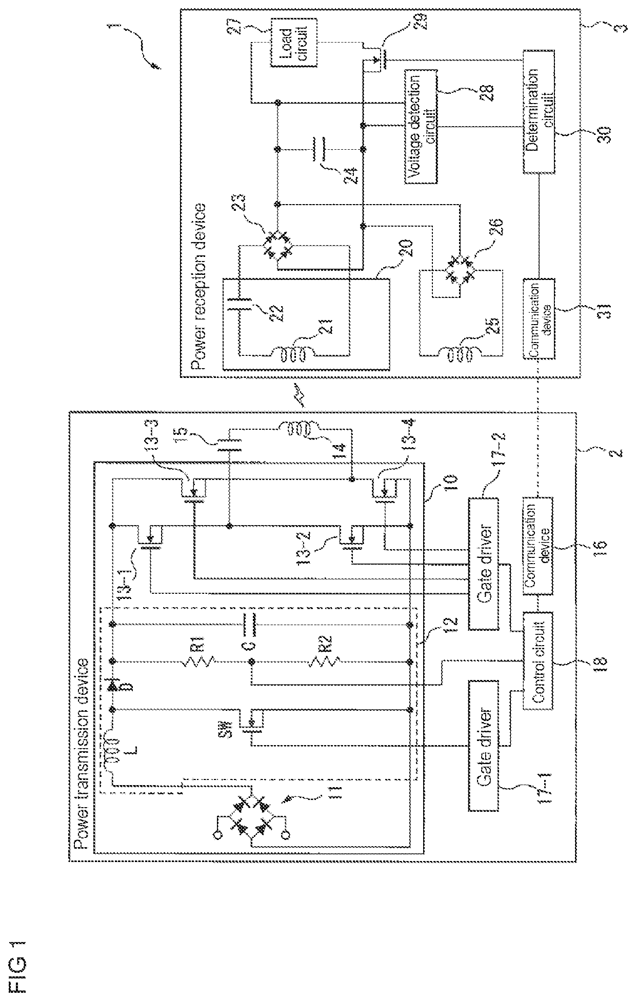
[0032]Hereinafter, a non-contact power feeding device according to one embodiment of the present invention will be described with reference to the drawings. In this non-contact power feeding device, a device on a power reception side is provided together with a reception coil, which is included in a resonant circuit for power reception and connected in series with a capacitor, to be capable of being electromagnetically coupled to the reception coil. Further, the device on the power reception side has a sub-coil having a number of turns smaller than the number of turns of the reception coil. Then, both terminals of the sub-coil are connected to a rectifier circuit, and both terminals of the rectifier circuit are respectively connected to both terminals of a smoothing capacitor configured to smooth an output voltage from the resonant circuit. This allows the non-contact power feeding device to prevent application of an excessive voltage to the resonant circuit with a current flowing f...


PUM


Abstract

A power reception device of a non-contact power feeding device has: a resonant circuit having a reception coil configured to receive electric power from a power transmission device and a resonant capacitor connected in series with the reception coil; a first rectifier circuit configured to rectify electric power received via the resonant circuit; a smoothing capacitor connected to the first rectifier circuit and configured to smooth a voltage outputted from the first rectifier circuit; a sub-coil arranged to be capable of being electromagnetically coupled to the reception coil; and a second rectifier circuit connected between the sub-coil and the smoothing capacitor, and configured to output electric power according to a voltage generated in the sub-coil to the smoothing capacitor in response to a voltage obtained by rectifying a voltage generated in the sub-coil being higher than a voltage between both terminals of the smoothing capacitor.

Description

TECHNICAL FIELD[0001]The present invention relates to a non-contact power feeding device.BACKGROUND ART[0002]Conventionally, there has been studied so-called non-contact power feeding (also called wireless power feeding) technology, in which electric power is transmitted through space without using a metal contact point or the like.[0003]In a power feeding device using non-contact power supply technology (hereinafter, simply referred to as a non-contact power feeding device), when a positional relationship between a coil on a primary side (a power transmission side) and a coil on a secondary side (a power reception side) fluctuates, a coupling degree between the two coils changes. As a result, an output voltage from a device of the power reception side to a load circuit also fluctuates. In some cases, the output voltage to the load circuit may rise excessively, causing a failure in the device on the power reception side or the load circuit. Therefore, a technique for suppressing an ...

Claims


Application Information

Patent Timeline
Patent Type & Authority Applications(United States)
IPC IPC(8): H02J50/12H02J50/40H02J50/80
CPCH02J50/12H02J50/80H02J50/40H02J50/402
Inventor NAKAO, GOROTABATA, KENICHIKAWAI, YUSUKENOMURA, ATSUSHITAKEYAMA, TAKAHIRONAKAJO, MASANOBU
Owner ORMON CORP
Why Eureka
Try Eureka