Method and device in nodes used for wireless communication
- Summary
- Abstract
- Description
- Claims
- Application Information
AI Technical Summary
Benefits of technology
Problems solved by technology
Method used
Image

Examples
embodiment 1
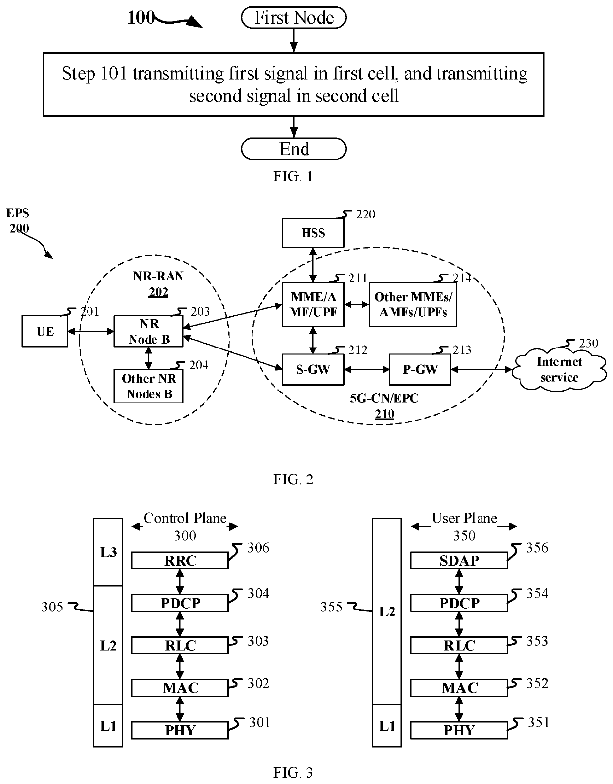
[0071]Embodiment 1 illustrates a flowchart of processing of a first node, as shown in FIG. 1. In 100 illustrated by the figure, each box represents a step. In Embodiment 1, a first node in the present disclosure transmits a first signal in a first cell and transmits a second signal in a second cell in step 101.
[0072]In Embodiment 1, a serving cell identity of the first cell is a first ID, while a serving cell identity of the second cell is a second ID, the first ID being smaller than the second ID; when the second cell is capable of scheduling a target cell, the second signal comprises first UCI; when the second cell is incapable of scheduling the target cell, the first signal comprises the first UCI.
[0073]In one embodiment, the first cell is a Serving Cell.
[0074]In one embodiment, the second cell is a Serving Cell.
[0075]In one embodiment, the first cell is a Secondary Cell.
[0076]In one embodiment, the second cell is a Secondary Cell.
[0077]In one embodiment, the first ID is a Servin...
embodiment 2
[0143]Embodiment 2 illustrates a schematic diagram of a network architecture, as shown in FIG. 2.
[0144]FIG. 2 is a diagram illustrating a network architecture 200 of 5G NR, Long-Term Evolution (LTE), and Long-Term Evolution Advanced (LTE-A) systems. The 5G NR or LTE network architecture 200 may be called an Evolved Packet System (EPS) 200 or other appropriate terms, which may comprise one or more UEs 201, an NG-RAN 202, an Evolved Packet Core / 5G Core Network (EPC / 5G-CN) 210, a Home Subscriber Server (HSS) 220 and an Internet Service 230. The EPS 200 may be interconnected with other access networks. For simple description, the entities / interfaces are not shown. As shown in FIG. 2, the EPS 200 provides packet switching services. Those skilled in the art will find it easy to understand that various concepts presented throughout the present disclosure can be extended to networks providing circuit switching services. The NG-RAN 202 comprises an NR node B (gNB) 203 and other gNBs 204. The...
embodiment 3
[0157]Embodiment 3 illustrates a schematic diagram of a radio protocol architecture of a user plane and a control plane according to the present disclosure, as shown in FIG. 3. FIG. 3 is a schematic diagram illustrating an embodiment of a radio protocol architecture of a user plane 350 and a control plane 300. In FIG. 3, the radio protocol architecture for a control plane 300 between a first communication node (UE, gNB or, RSU in V2X) and a second communication node (gNB, UE, or RSU in V2X) is represented by three layers, which are a layer 1, a layer 2 and a layer 3, respectively. The layer 1 (L1) is the lowest layer which performs signal processing functions of various PHY layers. The L1 is called PHY 301 in the present disclosure. The layer 2 (L2) 305 is above the PHY 301, and is in charge of the link between the first communication node and the second communication node via the PHY 301. The L2 305 comprises a Medium Access Control (MAC) sublayer 302, a Radio Link Control (RLC) su...
PUM
 Abstract
Description
Claims
Application Information
 - Generate Ideas
- Intellectual Property
- Life Sciences
- Materials
- Tech Scout
- Unparalleled Data Quality
- Higher Quality Content
- 60% Fewer Hallucinations
Browse by: Latest US Patents, China's latest patents, Technical Efficacy Thesaurus, Application Domain, Technology Topic, Popular Technical Reports.
© 2025 PatSnap. All rights reserved.Legal|Privacy policy|Modern Slavery Act Transparency Statement|Sitemap|About US| Contact US: help@patsnap.com