Linear LED light source and manufacturing method

Active Publication Date: 2021-11-11
FLOWIL INT LIGHTING HLDG BV
View PDF0 Cites 1 Cited by
  • Summary
  • Abstract
  • Description
  • Claims
  • Application Information

AI Technical Summary

Benefits of technology

The present invention provides a method for manufacturing linear LED light sources in which the LED units are positioned close to the ends of the sealed glass envelope, allowing for a more efficient use of space. Additionally, isolating bridges are provided between the support frames to improve mechanical stability without blocking emitted light. The technical effects are improved performance and stability of the LED light sources.

Problems solved by technology

The reason is that LED filaments are omnidirectional light sources, and they therefore cannot be attached to a conventional heat sink (for instance a metallic or thermally conductive polymer substrate) owing to the opaque nature of such heat sinks.
This would block the radiation of light in one direction and render the concept of the omnidirectional LED filament useless.
However the permeability through ordinary soft glasses is sufficiently slow that such gases can be contained within envelopes made of these materials sufficiently long to attain a useful lamp lifetime.
The formation of such seals calls for the fusion of the glass at high temperatures, which may be deleterious to the LED filaments in close proximity owing to the use of polymeric and other thermally unstable materials in their construction.
This leads to the formation of a non light-emitting dead zone in the vicinity of the seal formation region.
Owing to the incineration and destruction of the LEDs when they are brought closer to a seal formation region of the glass tube, the production of double-ended LED filament tube lamps has proven particularly difficult.

Method used


Image

  • Linear LED light source and manufacturing method
  • Linear LED light source and manufacturing method
  • Linear LED light source and manufacturing method

Examples


Embodiment Construction

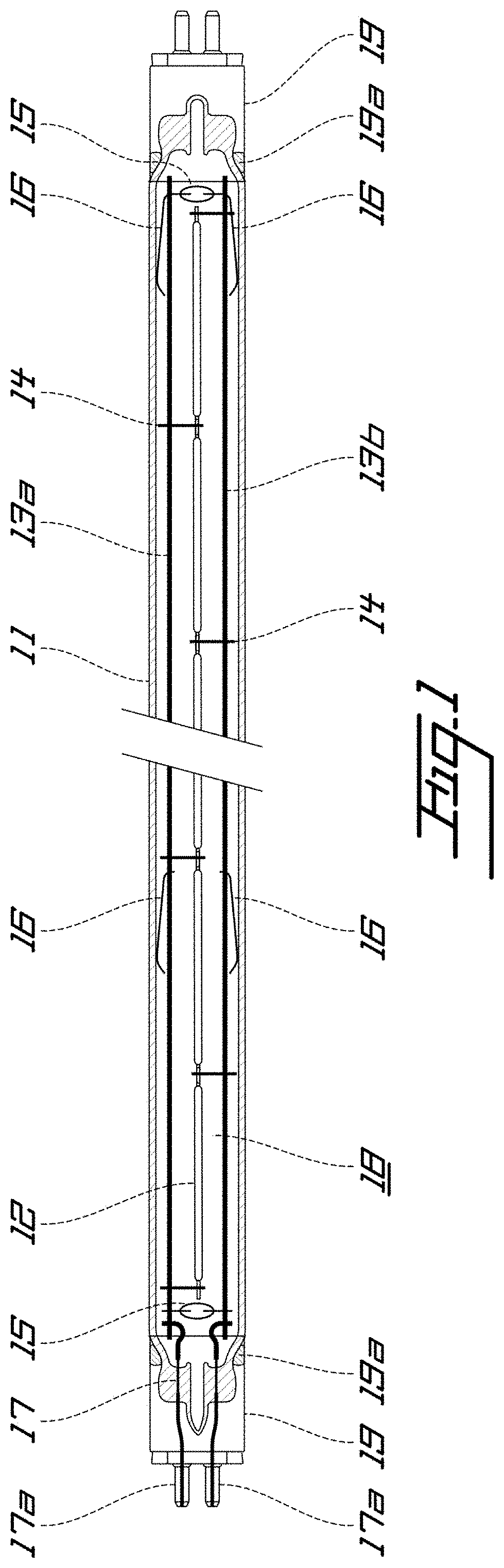
[0070]FIG. 1 is a schematic view of a linear LED light source according to an embodiment of the present invention. The linear LED light source comprises a sealed lamp envelope 11 of essentially cylindrical shape that is translucent and made of glass. A light source mount assembly 10 is arranged inside the sealed lamp envelope 11. In the present embodiment, the light source assembly 10 comprises multiple LED units 12 mounted to metallic support frames 13a, 13b optionally via metallic spacer components 14, isolating bridges 15 and buffer springs 16.

[0071]The light source assembly 10 is connected to an electrical feedthrough component 17. Specifically, the metallic support frames 13a, 13b are conductively connected, e.g. welded or soldered to the electrical feedthrough component 17.

[0072]The LED units 12 of the present embodiment are constituted by LED filaments. The LED units 12 are sequentially aligned along the longitudinal axis of the sealed lamp envelope 11 and disposed essentiall...


PUM


Abstract

The present invention relates to a method for manufacturing a linear LED light source, comprising: providing a tubular glass envelope that is open at its proximal end and its distal end; inserting a light source mount assembly comprising one or more LED units into the tubular glass envelope; forming a distal hermetic seal at the distal end such that a distal opening remains at the distal end; forming a proximal hermetic seal at the proximal end such that a proximal opening remains at the proximal end; filling the tubular glass envelope with a gas filling; and sealing the distal and proximal openings to obtain a sealed lamp envelope; wherein a flow of coolant gas through the tubular glass envelope is maintained during the formation of the proximal hermetic seal and / or distal hermetic seal if the light source mount assembly is inserted before the formation of the respective hermetic seal.

Description

CROSS-REFERENCE TO RELATED APPLICATION[0001]The present application is a § 371 U.S. National Phase Entry of International Patent Application No. PCT / EP2018 / 076686, filed on Oct. 1, 2018, the entirety of which is hereby incorporated herein by reference.TECHNICAL FIELD[0002]The present invention relates to a manufacturing method for a linear LED light source, and a linear LED light source.BACKGROUND[0003]In LED filament light sources, light is generated by means of LED filaments—multi-LED structures that resemble the filament of an incandescent light bulb. LED filaments consist of multiple LEDs connected in series on a transparent substrate, allowing the light emitted by the LEDs to disperse evenly and uniformly. Commonly, a coating of yellow phosphor in a resin binder material converts the blue light generated by the LEDs into white light. An example for a LED filament light source is disclosed in U.S. Pat. No. 8,400,051 B2.[0004]LED filament lamps are conventionally filled with a th...

Claims


Application Information

Patent Timeline
IPC IPC(8): F21V29/60F21V31/00F21K9/90F21K9/272
CPCF21V29/60F21V31/005F21Y2115/10F21K9/272F21K9/90F21K9/27F21V31/04F21Y2103/10
Inventor HOOKER, JAMESBROEDERS, FRANKSCHAAF, WALTER
Owner FLOWIL INT LIGHTING HLDG BV
Why Eureka
Try Eureka