Radio frequency module and communication device

a technology of radio frequency modules and communication devices, applied in the direction of digital transmission, time-division multiplexing, electrical devices, etc., can solve the problems of increased transfer loss, inability to provide isolation between signals, etc., and achieve the effect of low-loss transfer of signals

Active Publication Date: 2021-11-11
MURATA MFG CO LTD
View PDF10 Cites 3 Cited by
  • Summary
  • Abstract
  • Description
  • Claims
  • Application Information

AI Technical Summary

Benefits of technology

[0007]The present disclosure has been conceived in view of the foregoing problem, and its aim is to provide a radio frequency module and a communication device that enable low-loss transfer of signals in TDD communication bands.

Problems solved by technology

However, as recognized by the present inventor, in transferring radio frequency signals in these broad communication bands for TDD, the conventional technology fails to provide isolation between a signal path through which a radio frequency signal in such a broad TDD communication band is transferred and a signal path through which a radio frequency signal in an adjacent communication band is transferred.
This results in an increase in transfer loss.

Method used


Image

  • Radio frequency module and communication device
  • Radio frequency module and communication device
  • Radio frequency module and communication device

Examples


embodiment 1

1.1 Configurations of Radio Frequency Module 1 and Communication Device 6

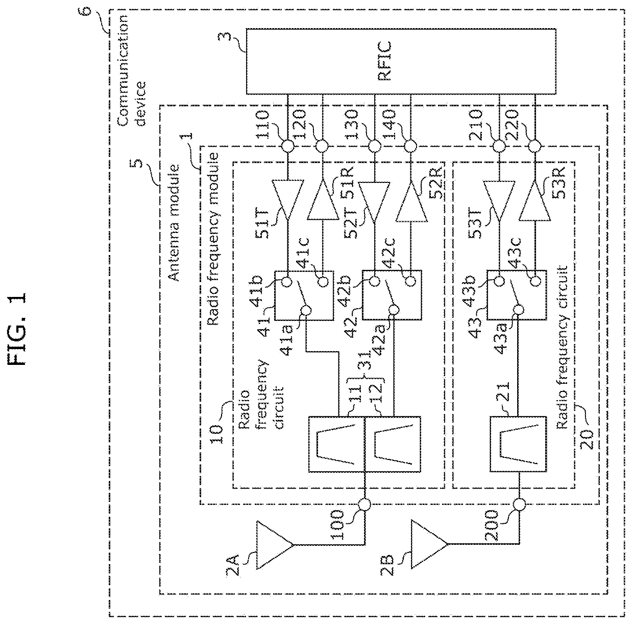
[0029]FIG. 1 is a diagram showing the circuit configurations of radio frequency module 1 and communication device 6 according to Embodiment 1. As shown in FIG. 1, communication device 6 includes radio frequency module 1, antennas 2A and 2B, and radio frequency (RF) signal processing circuit (RFIC) 3.

[0030]RFIC 3 is an exemplary RF signal processing circuit that processes radio frequency signals that are to be transmitted or have been received by antennas 2A and 2B. More specifically, RFIC 3 performs signal processing, such as down-conversion, on a reception signal input via radio frequency module 1, and outputs the resulting reception signal to a baseband signal processing circuit (BBIC: not illustrated). Also, RFIC 3 outputs, to radio frequency module 1, a transmission signal that has been processed on the basis of a signal input from the BBIC.

[0031]Antenna 2A is connected to radio frequency circuit 10 of radi...

embodiment 2

[0067]While the radio frequency module according to Embodiment 1 includes radio frequency circuits 10 and 20 that are connected to different antennas, the radio frequency module according to the present embodiment includes radio frequency circuits 10 and 20 that are connected to the same antenna 2.

2.1 Configuration of Radio Frequency Module 1A

[0068]FIG. 4 is a diagram showing the circuit configurations of radio frequency module 1A and antenna module 5A according to Embodiment 2.

[0069]Antenna module 5A includes antenna 2 and radio frequency module 1A. Antenna module 5A according to the present embodiment is different from antenna module 5 according to Embodiment 1 in that a single antenna 2 is disposed and that radio frequency module 1A includes switch 40. The following omits the descriptions of the same points as those of antenna module 5 and radio frequency module 1 according to Embodiment 1 and focuses on the differences to describe antenna module 5A and radio frequency module 1A ...

embodiment 3

[0087]While the radio frequency modules according to Embodiments 1 and 2 have the circuit configuration for transferring signals in the first through third communication bands, the radio frequency module according to the present embodiment has a configuration that further includes a circuit for transferring signals in a fourth communication band.

[0088]FIG. 5 is a diagram showing the circuit configurations of radio frequency module 1B and antenna module 5B according to Embodiment 3.

[0089]Antenna module 5B includes antennas 2A and 2B, and radio frequency module 1B. Antenna module 5B according to the present embodiment is different from antenna module 5 according to Embodiment 1 in the circuit configuration of radio frequency circuit 20B included in radio frequency module 1B. The following omits the descriptions of the same points as those of antenna module 5 and radio frequency module 1 according to Embodiment 1 and focuses on the difference to describe antenna module 5B and radio fre...


PUM


Abstract

A radio frequency module includes: a first antenna connection terminal; a second antenna connection terminal different from the first antenna connection terminal; a first filter having a passband of a first frequency range including a first communication band allocated as a TDD communication band; a second filter having a passband of a second frequency range including a second communication band allocated as a TDD communication band; and a third filter having a passband of a third frequency range including a third communication band allocated as a TDD communication band. The third frequency range is located between the first frequency range and the second frequency range. The first and second filters are both connected to one of the first antenna connection terminal and the second antenna connection terminal. The third filter is connected to the other of the first antenna connection terminal and the second antenna connection terminal.

Description

CROSS REFERENCE TO RELATED APPLICATION[0001]The present application is based on and claims priority to Japanese Patent Application No. 2020-083277 filed on May 11, 2020. The entire disclosure of the above-identified application, including the specification, drawings and claims is incorporated herein by reference in its entirety.TECHNICAL FIELD[0002]The present disclosure relates to radio frequency modules and communication devices.BACKGROUND[0003]To enable faster and higher-capacity communications, recent communications services have been working towards broadening communication bandwidth and making a simultaneous use of communication bands.[0004]Japanese Unexamined Patent Application Publication No. 2006-128881 discloses a multiplexer capable of duplexing and multiplexing radio frequency signals in two different communication bands. Such multiplexer includes an LC filter including an inductor and a capacitor, and is capable of duplexing and multiplexing radio frequency signals in b...

Claims


Application Information

Patent Timeline
Patent Type & Authority Applications(United States)
IPC IPC(8): H04L5/14H04L5/00H04L5/26
CPCH04L5/1469H04L5/26H04L5/0005H04B1/40H04B1/0064H04B1/0057
Inventor MORI, HIROTSUGU
Owner MURATA MFG CO LTD
Why Eureka
Try Eureka