Asymmetric directional coupler, adjustable mode generator and optical circulator

A directional coupler, asymmetric technology, applied in the direction of instruments, light guides, optics, etc., can solve the problems of complex process, volatility, and large size of optical switches

Pending Publication Date: 2022-05-31
NAT UNIV OF DEFENSE TECH
View PDF0 Cites 3 Cited by
  • Summary
  • Abstract
  • Description
  • Claims
  • Application Information

AI Technical Summary

Problems solved by technology

[0007] The technical problem to be solved by the present invention is to overcome the shortcomings of existing optical switches such as complex process, volatility, and large size, and to provide a phase-change material based on direct binary search (Direct-binary-search, DBS) algorithm optimization. Silicon based asymmetric directional coupler

Method used


Image

  • Asymmetric directional coupler, adjustable mode generator and optical circulator
  • Asymmetric directional coupler, adjustable mode generator and optical circulator
  • Asymmetric directional coupler, adjustable mode generator and optical circulator

Examples


Embodiment 1

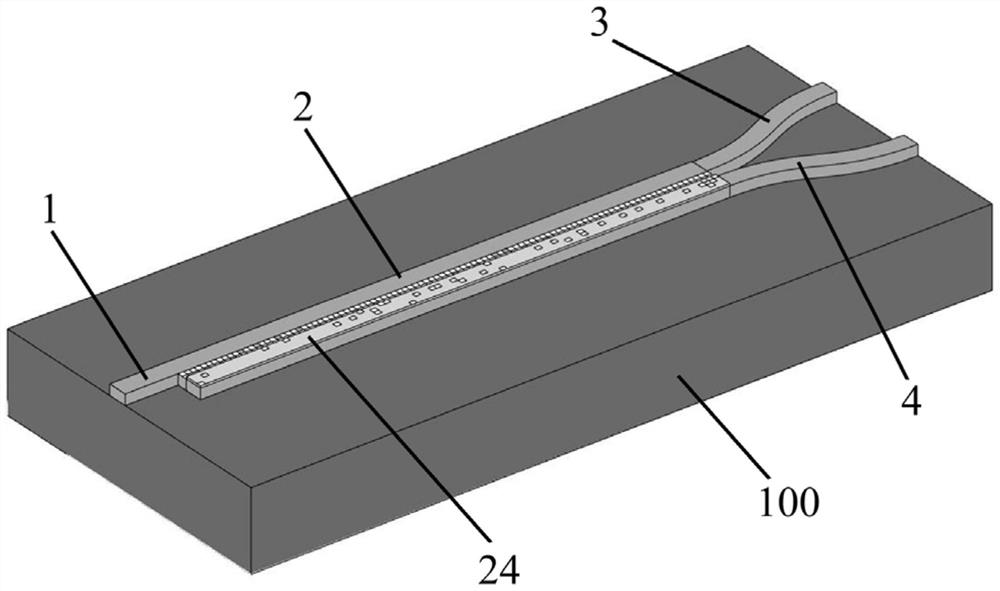
[0034] Please also refer to Figure 1-5 , the asymmetric directional coupler provided by the present invention includes a substrate 100, on which a top layer of silicon is provided, and the top layer of silicon includes a first port 1, a coupling region 2, a first output waveguide 3 and a second output A waveguide 4, one end of the coupling region 2 is connected to the first port 1, and the other end is connected to the first output waveguide 3 and the second output waveguide 4, the coupling region 2 is covered with a phase-change material layer 24, and the coupling region 2 It is divided into N×M rectangular units, and by adjusting the state of the rectangular units, an aperiodic first perforated array meeting the predetermined first output target is formed, and the first output target refers to the first output waveguide 3 and the sum of the transmittance of the second output waveguide 4.

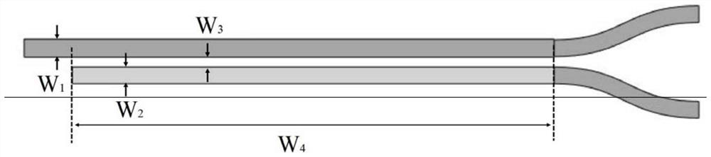
[0035]More specifically, the coupling region 2 includes an upper waveguide 21, a low...

Embodiment 2

[0054] Please also refer to Figure 6-9 , the present embodiment provides a controllable mode generator, including the above-mentioned asymmetric directional coupler, the mode division multiplexer optimization area 5 and the third output waveguide 6, and one end of the mode division multiplexer optimization area 5 is respectively It is connected to the first output waveguide 3 and the second output waveguide 4, and the other end is connected to the third output waveguide 6. The mode division multiplexer optimization area 5 is divided into X×Y fourth rectangular units 51, by adjusting the The state of the fourth rectangular unit 51 forms an aperiodic second perforated array that satisfies a predetermined second output target, and the second output target refers to the transmittance of two different output modes in the third output waveguide 6 Sum.

[0055] More specifically, the two different modes are from 1540nm to 1560nm band TE 0 mode and TE from 1540nm to 1560nm 1 mode,...

Embodiment 3

[0064] Please also refer to Figure 10-12 , the present invention also provides an optical circulator, including the above-mentioned asymmetric directional coupler, a plurality of asymmetric directional couplers form a circular array, and the first output waveguide 3 of one said asymmetric directional coupler is connected to the adjacent asymmetric directional coupler. The second output waveguide 4 of the symmetrical directional coupler is connected.

[0065] In this embodiment, the first output waveguide 3 is connected with the second output waveguide 4 to form a curved waveguide, and the optical circulator is composed of four asymmetric directional couplers 11-14 through the first curved waveguide 15 and the second curved waveguide 16 respectively. , the third curved waveguide 17 , and the fourth curved waveguide 18 are connected in series in sequence, and the two ends of each curved waveguide have the same width as the connecting part.

[0066] It can be understood that, a...


PUM

PropertyMeasurementUnit
thicknessaaaaaaaaaa
thicknessaaaaaaaaaa
lengthaaaaaaaaaa

Abstract

The invention provides an asymmetric directional coupler which comprises a substrate, top silicon is arranged on the substrate and comprises a first port, a coupling area, a first output waveguide and a second output waveguide, one end of the coupling area is connected with the first port, and the other end of the coupling area is connected with the first output waveguide and the second output waveguide. The coupling area is covered with a phase change material layer, the coupling area is divided into N * M rectangular units, a non-periodic first punching array meeting a preset first output target is formed by adjusting the state of the rectangular units, and the first output target refers to the sum of the transmittance of the first output waveguide and the transmittance of the second output waveguide; the asymmetric directional coupler provided by the invention is small in size, easy to process, stable in performance and capable of realizing regulation and control of a light propagation path.

Description

technical field [0001] The invention belongs to the technical field of micro-nano optoelectronic components, and in particular relates to an asymmetric directional coupler, an adjustable mode generator, and an optical circulator. Background technique [0002] Silicon photonics is a very promising optical interconnect platform due to its compatibility with existing complementary metal-oxide semiconductor (CMOS) technologies and dense integration technologies. Photonics integrated circuits (PICs) have also achieved tremendous development in the past decade. [0003] Today, the most advanced photonic integrated circuits can already integrate hundreds or thousands of optical devices. Among them, the optical switch is an essential component, which is used for the dynamic routing of light in different paths. On-chip optically tunable devices are usually realized based on electro-optic or thermo-optic effects, both of which use electricity or heat to act on the waveguide, thereby...

Claims


Application Information

Patent Timeline
Patent Type & Authority Applications(China)
IPC IPC(8): G02B6/293
CPCG02B6/293G02B6/2934
Inventor 马汉斯罗鸣宇高慧琴杨俊波方粮
Owner NAT UNIV OF DEFENSE TECH
Why Eureka
Try Eureka