Redox flow battery and battery system

a battery and flow technology, applied in the field of redox flow battery and battery system, can solve the problems of increasing system size and cost, increasing system size, uneven cell stack compression, etc., and achieves the effects of reducing battery environmental footprint, low cost, and reducing performance losses

Active Publication Date: 2021-11-18
ESS TECHNOLOGY
View PDF1 Cites 0 Cited by
  • Summary
  • Abstract
  • Description
  • Claims
  • Application Information

AI Technical Summary

Benefits of technology

[0003]Redox flow batteries are suitable for grid scale storage applications due to their capability for scaling power and capacity independently, as well as for charging and discharging over thousands of cycles with reduced performance losses in comparison to conventional battery technologies. Iron hybrid redox flow battery are particularly attractive due to the incorporation of low cost materials in the cells stack. The iron redox flow battery (IFB) relies on iron, salt, and water for electrolyte. These earth abundant and inexpensive materials used in the IFB along with the omission of harsh chemical, in some embodiment, reduces the battery's environmental footprint.

Problems solved by technology

However, the inventors have recognized scaling challenges may arise when designing flow battery systems to meet varying end-use power and / or storage capacity goals.
For instance, deploying multiple flow battery units in a single system may significantly increase the system's size and cost due to the large number of redundant components in the battery system such as pressure plates, housing, etc.
Furthermore, previous stack compression systems and reinforcement structures have exhibited space inefficiencies and uneven cell stack compression.
Uneven cell compression may lead to unwanted battery flow fields and a decrease in battery output, efficiency, and in some cases structural integrity.

Method used


Image

  • Redox flow battery and battery system
  • Redox flow battery and battery system
  • Redox flow battery and battery system

Examples


Embodiment Construction

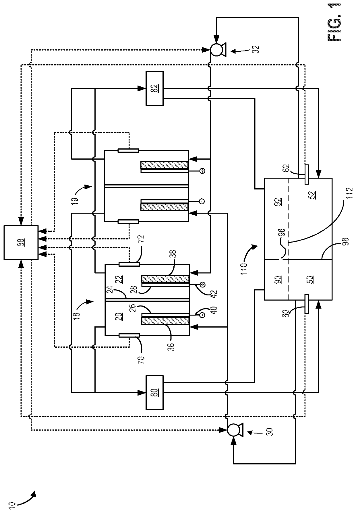
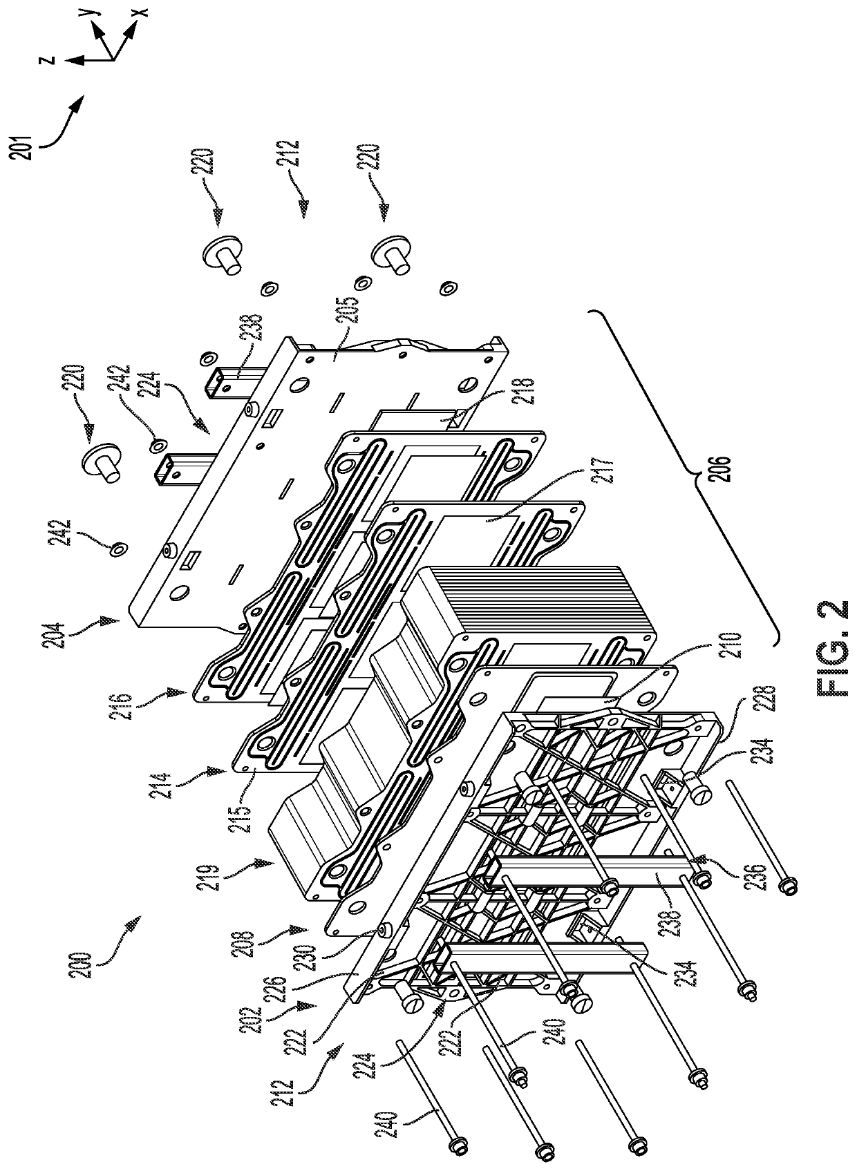
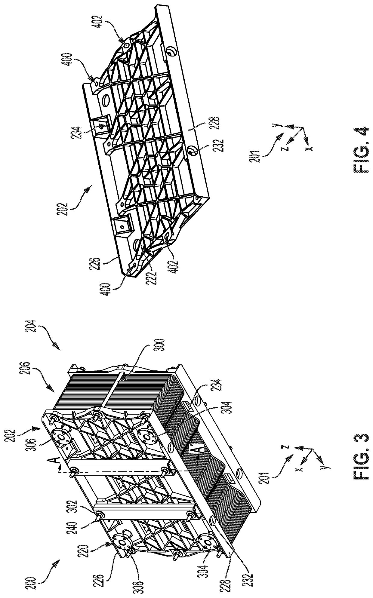
[0031]The following description relates to systems and methods serving to reduce manufacturing costs of a redox flow battery. To achieve the reduced manufacturing cost the battery system may include a space efficient compression assembly designed to both compress the cell stack and structurally reinforce the battery. The compression assembly may achieve the aforementioned benefits via leaf springs that extend down the sides of the pressure plates and exert an inward preload force on the cell stack. Leaf springs compactly provide cell stack compression to reduce (e.g., prevent) deflection of active areas in the battery during operation. The pressure plates may include reinforcing ribs that allow the compression assembly to be structurally reinforced.

[0032]The redox flow battery may further include modular features that allow the battery system to be cost effectively scaled, as desired. For instance, pressure plates in the battery may incorporate stacking protrusions and detents in fl...


PUM

PropertyMeasurementUnit
angleaaaaaaaaaa
pressureaaaaaaaaaa
forceaaaaaaaaaa

Abstract

A redox flow battery and battery system are provided. In one example, the redox flow battery includes a set of pressure plates having a first pressure plate at a first terminal end and a second pressure plate at a second terminal end, the second terminal end and the first terminal end positioned on opposing longitudinal sides of the redox flow battery. The redox flow battery further includes a first cell stack positioned longitudinally between the first pressure plate and the second pressure plate, each of the first and second pressure plates includes a plurality stacking detents on a first flange and a plurality of stacking protrusions on a second flange, and the first flange and the second flange arranged on opposing vertical sides of the redox flow battery.

Description

CROSS-REFERENCE TO RELATED APPLICATION[0001]The present application claims priority to U.S. Provisional Application No. 63 / 025,312, entitled “REDOX FLOW BATTERY AND BATTERY SYSTEM”, and filed on May 15, 2020. The entire contents of the above-listed application are hereby incorporated by reference for all purposes.FIELD[0002]The present description relates generally to a redox flow battery and battery system.BACKGROUND AND SUMMARY[0003]Redox flow batteries are suitable for grid scale storage applications due to their capability for scaling power and capacity independently, as well as for charging and discharging over thousands of cycles with reduced performance losses in comparison to conventional battery technologies. Iron hybrid redox flow battery are particularly attractive due to the incorporation of low cost materials in the cells stack. The iron redox flow battery (IFB) relies on iron, salt, and water for electrolyte. These earth abundant and inexpensive materials used in the I...

Claims


Application Information

Patent Timeline
Patent Type & Authority Applications(United States)
IPC IPC(8): H01M8/18H01M8/0438
CPCH01M8/188H01M8/0438Y02E60/50H01M8/04186
Inventor CASEY, SEANEVANS, CRAIGGROBERG, THIAGOSONG, YANG
Owner ESS TECHNOLOGY
Why Eureka
Try Eureka