Redox flow battery and battery system

a flow battery and battery technology, applied in the direction of regenerative fuel cells, fuel cells, electrical equipment, etc., can solve the problems of reducing energy transfer efficiency and battery performance, thermal degradation of cell stack components, and unwanted shunt current generation of previous flow batteries, so as to reduce the environmental footprint of the battery, reduce the loss of performance, and low cost

Pending Publication Date: 2021-11-18
ESS TECHNOLOGY
View PDF5 Cites 0 Cited by
  • Summary
  • Abstract
  • Description
  • Claims
  • Application Information

AI Technical Summary

Benefits of technology

[0003]Redox flow batteries are suitable for grid scale storage applications due to their capability for scaling power and capacity independently, as well as for charging and discharging over thousands of cycles with reduced performance losses in comparison to conventional battery technologies. Iron hybrid redox flow battery are particularly attractive due to the incorporation of low cost materials in the cell stack. The iron redox flow battery (IFB) relies on iron, salt, and water for electrolyte. These earth abundant and inexpensive materials in the IFB along with the omission of harsh chemicals, in some embodiments, reduces the battery's environmental footprint.

Problems solved by technology

Previous flow batteries generate unwanted shunt currents due to the electrically conductive electrolyte traveling through battery flow channels.
Shunt currents in the electrolyte flow can give rise to decreased energy transfer efficiency and battery performance.
Heat generated by the shunt currents may also result in thermal degradation of cell stack components.
Furthermore, fluid paths, in previous flow batteries, may be inefficient with regard to compactness.
Electrolyte fluid draining has also presented issues in prior flow battery designs.

Method used


Image

  • Redox flow battery and battery system
  • Redox flow battery and battery system
  • Redox flow battery and battery system

Examples


Embodiment Construction

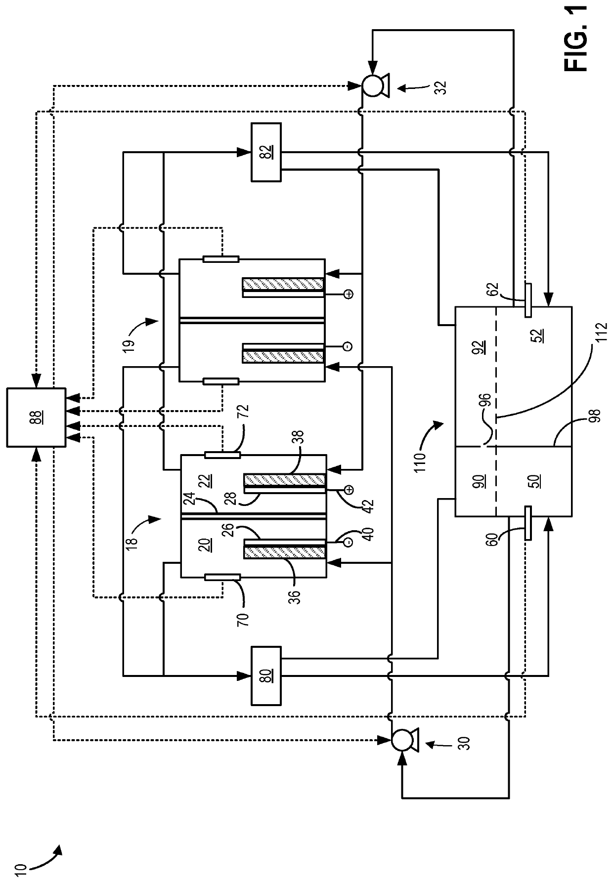
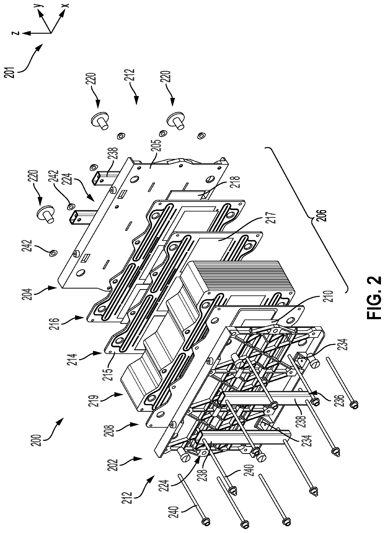
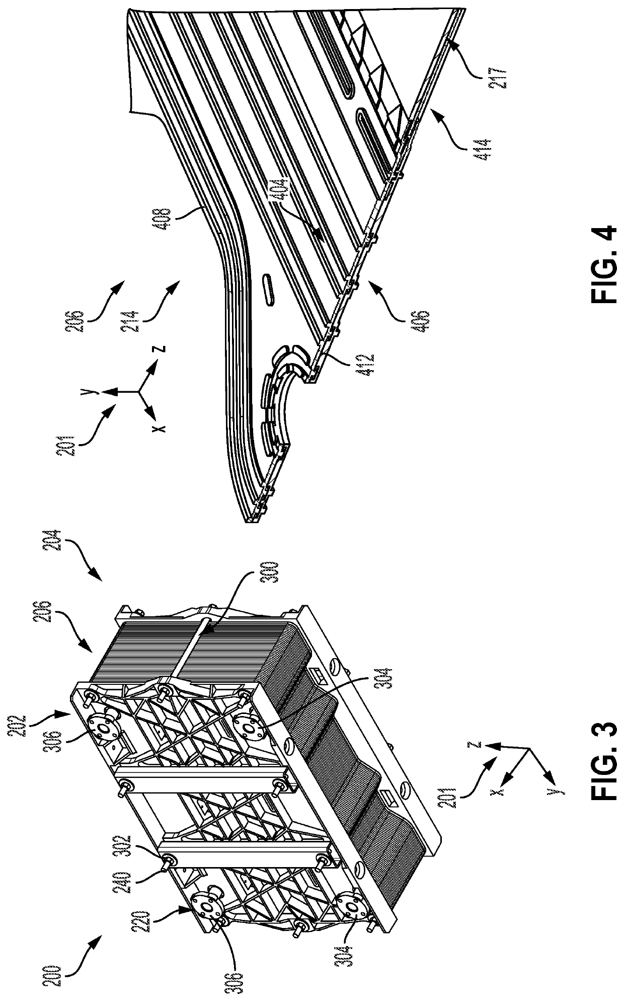
[0029]The following description relates to flow battery systems and manufacturing techniques serving to increase system compactness as well as reduce shunt currents in the battery cell stack. In one example, the flow battery system may include a cell stack having sequentially arranged bipolar and membrane frame assemblies with tongue and groove interfaces formed therebetween. The tongue and groove interfaces space efficiently delimit different electrolyte flow channels in the stack. Further in one example, the electrolyte flow channels may include serpentine shaped shunt channels configured to flow electrolyte therethrough. The serpentine shape allows the length of the shunt channels to be increased, thereby reducing shunt current generation during battery operation. The frame assemblies in the cell stack may also include nested alignment bosses. The alignment bosses allow for quick and efficient cell stack construction (e.g., simplified manufacturing automation) and reduce the like...


PUM

PropertyMeasurementUnit
volume ratioaaaaaaaaaa
aspect ratioaaaaaaaaaa

Abstract

A redox flow battery and battery system are provided. In one example, the redox flow battery includes a cell stack assembly interposed by two endplates, the cell stack assembly includes a plurality of mated membrane frame plates and bipolar frame plates. For each pair of mated membrane and bipolar frame plates a negative shunt channel and a positive shunt channel are formed and the negative and positive shunt channels are in fluidic communication with a plurality of inlet and outlet distribution channels that are in fluidic communication with at least one bipolar plate.

Description

CROSS-REFERENCE TO RELATED APPLICATION[0001]The present application claims priority to U.S. Provisional Application No. 63 / 025,316, entitled “REDOX FLOW BATTERY AND BATTERY SYSTEM”, and filed on May 15, 2020. The entire contents of the above-listed application are hereby incorporated by reference for all purposes.FIELD[0002]The present description relates generally to a redox flow battery and battery system.BACKGROUND AND SUMMARY[0003]Redox flow batteries are suitable for grid scale storage applications due to their capability for scaling power and capacity independently, as well as for charging and discharging over thousands of cycles with reduced performance losses in comparison to conventional battery technologies. Iron hybrid redox flow battery are particularly attractive due to the incorporation of low cost materials in the cell stack. The iron redox flow battery (IFB) relies on iron, salt, and water for electrolyte. These earth abundant and inexpensive materials in the IFB alo...

Claims


Application Information

Patent Timeline
Patent Type & Authority Applications(United States)
IPC IPC(8): H01M8/18H01M8/2455
CPCH01M8/188H01M8/2455Y02E60/50H01M8/2459H01M8/0263H01M8/0258
Inventor EVANS, CRAIG E.CASEY, SEANGROBERG, THIAGOSONG, YANG
Owner ESS TECHNOLOGY
Why Eureka
Try Eureka