Determining Light Settings and/or Daylight Blocker Settings Based on Data Signal Quality

a technology of data signal quality and light setting, applied in the direction of electromagnetic transmission, electrical equipment, close-range type systems, etc., can solve the problems of inability to operate lifi and light source needs to be brighter

Active Publication Date: 2021-11-18
SIGNIFY HLDG BV
View PDF0 Cites 0 Cited by
  • Summary
  • Abstract
  • Description
  • Claims
  • Application Information

AI Technical Summary

Benefits of technology

[0023]Said at least one processor may be configured to determine one or more user device positions of and/or for one or more user devices receiving said data signal and/or one or more user device positions of and/or for one or more user devices not receiving said data signal, determine one or more light transmission positions of one or more lights of said set of lights and/or said further set of lights and/or of one or more daylight blockers of said set of daylight blockers, and determine said first set of light settings for said set of lights, said first set of light settings

Problems solved by technology

One of the limitations of LiFi is that the light source needs to be brighter than a certain threshold.
Otherwise, LiFi would not be a

Method used


Image

  • Determining Light Settings and/or Daylight Blocker Settings Based on Data Signal Quality
  • Determining Light Settings and/or Daylight Blocker Settings Based on Data Signal Quality
  • Determining Light Settings and/or Daylight Blocker Settings Based on Data Signal Quality

Examples


first embodiment

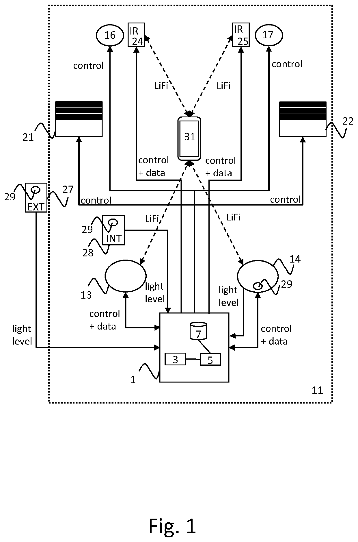
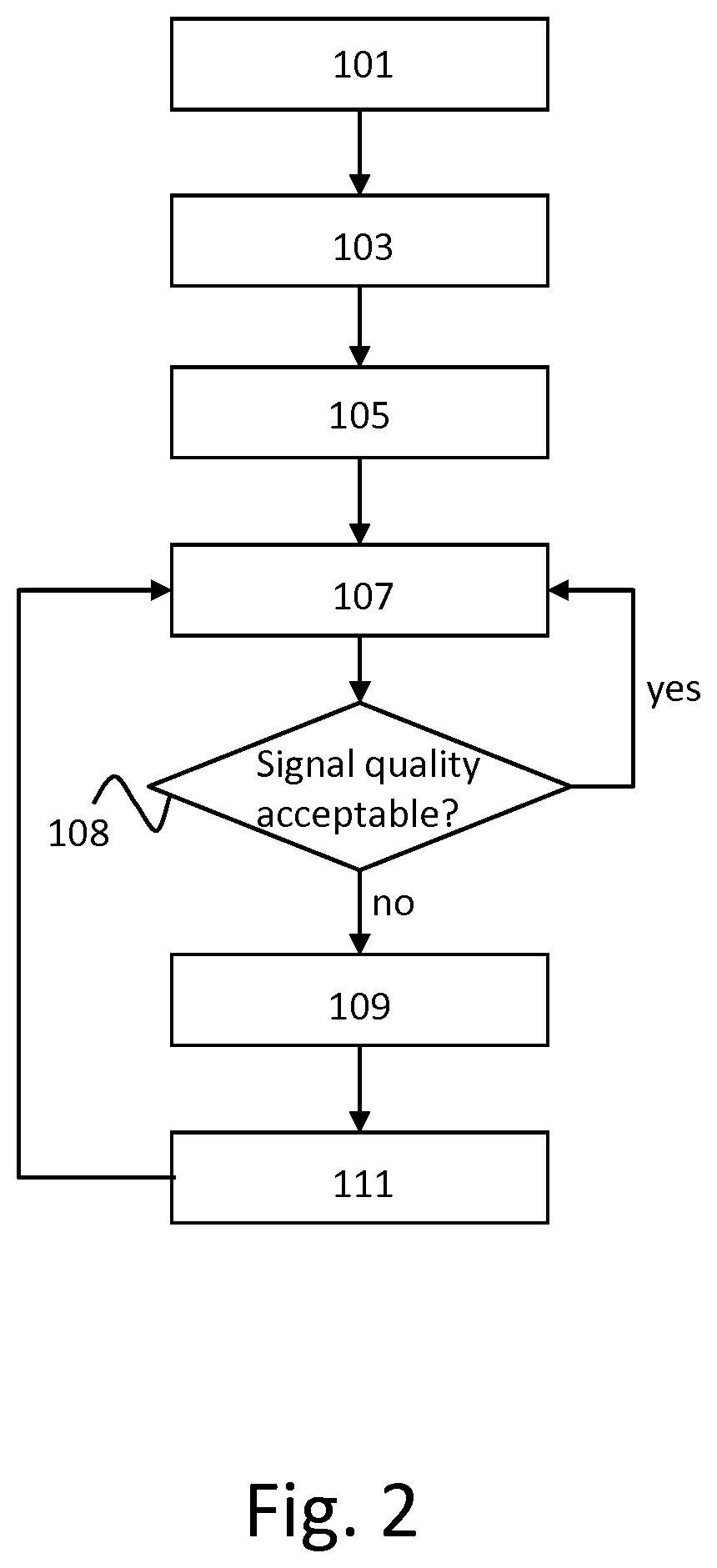
[0058]the method of the invention is shown in FIG. 2. In this embodiment, the method does not control lights 16, 17, 24 and 25 of FIG. 1. A step 101 comprises obtaining a target light level. In this embodiment, the target light level is a target light level for visible light. A step 103 comprises determining a first set of light settings for lights 13 and 14 and a first set of daylight blocker settings for daylight blockers 21 and 22 based on the target light level. A step 105 comprises controlling the lights 13 and 14 based on the first set of light settings and the daylight blockers 21 and 22 based on the first set of daylight blocker settings.

[0059]A step 107 comprises receiving from the user device 31 information indicating a quality of a data signal received by the user device from one or more lights of the set of lights. The data signal is transmitted by modulating a light signal. The signal quality is determined by the user device 31. A step 108 comprises determining whether ...

second embodiment

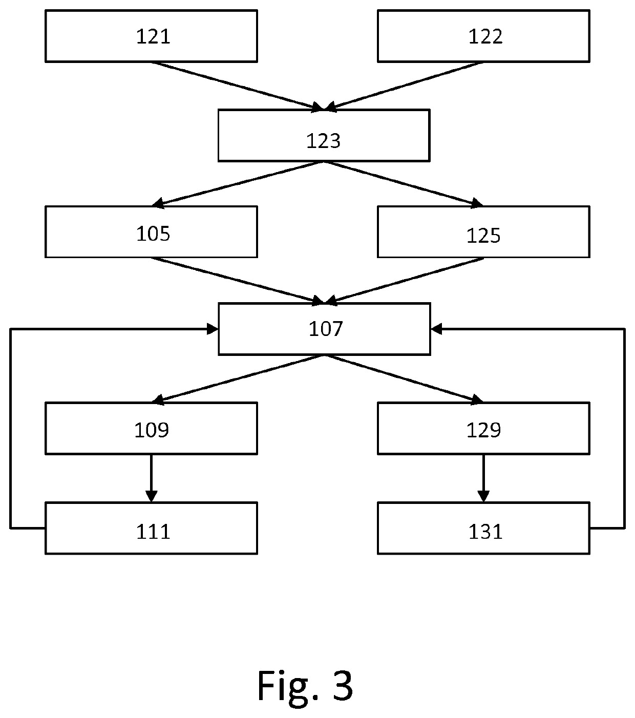
[0062]the method of the invention is shown in FIG. 3. In this embodiment, the method does not control lights 24 and 25 of FIG. 1. Steps 121 and 122 replace step 101 of FIG. 2. Step 121 comprises obtaining a target light level for lights transmitting data. Step 122 comprises obtaining a target visible light level. Step 123 replaces step 103 of FIG. 2. Step 123 comprises determining the first set of light settings for lights 13 and 14, the first set of daylight blocker settings for daylight blockers 21 and 22, and a first set of further light settings for lights 16 and 17 based on the target light level for lights transmitting data and the target visible light level.

[0063]For example, the light settings for lights 13 and 14 may first be determined such that the target light level is achieved and next, the settings for the lights 16 and 17 and for the daylight blockers 21 and 22 may be determined such that the target visible light level is achieved. The lights 13 and 14 include only li...

third embodiment

[0067]the method of the invention is shown in FIG. 4. In this embodiment, the method does not control lights 24 and 25 of FIG. 1. Step 101 comprises obtaining a target light level. In this embodiment, the target light level is a target light level for visible light. A step 151 comprises obtaining a measured light level, e.g. from light sensor device 28 or LiFi light 14. Step 153 comprises checking whether the measured light level falls in a range of acceptable values, e.g. 390-410 lux, 580-620 lux, or 600+ lux. If it does not, steps 103 and 105 are performed. If it does, steps 103 and 105 are skipped.

[0068]In the embodiment of FIG. 4, step 103 comprises a sub step 155. Step 155 comprises determining a first set of light settings for lights13, 14, 16, and 17 and a first set of daylight blocker settings for daylight blockers 21 and 22 based on the target light level and the measured light level. Step 105 comprises controlling the lights 13, 14, 16, and 17 based on the first set of lig...


PUM


Abstract

A system (1) is configured to obtain a target light level, determine a first set of light settings for one or more lights (13,14,24,25) and/or a first set of daylight blocker settings for one or more daylight blockers (21,22) based on the target light level, control these devices based on the first set(s) of settings, and receive from a user device (31) information indicating a quality of a light-modulated data signal received by the user device from the one or more lights, as determined by the user device. The system is further configured to determine a second set of light settings based on the first set of light settings and the determined signal quality and/or a second set of daylight blocker settings based on the first set of daylight blocker settings and the determined signal quality and control these devices based on the second set(s) of settings.

Description

FIELD OF THE INVENTION[0001]The invention relates to a system for determining light settings and / or daylight blocker settings.[0002]The invention further relates to a method of determining light settings and / or daylight blocker settings.[0003]The invention also relates to a computer program product enabling a computer system to perform such a method.BACKGROUND OF THE INVENTION[0004]Intelligent light controls have been recognized as one of the most economically viable measures to decrease energy consumption and greenhouse gas emission. Total Light Management (TLM) systems that combine automatic control of blinds and lights gained in attention due to their potential to cut lighting energy costs 30-60% dependent on the climate in commercial buildings. The main aspect of a TLM system is that it balances daylight and artificial lighting, pursuing two goals maximizing daylight (energy considerations) and maintaining a preferred light level.[0005]Total Light Management control offers an au...

Claims


Application Information

Patent Timeline
IPC IPC(8): H05B47/11H04B10/079H04B10/516H05B47/19
CPCH05B47/11H05B47/19H04B10/516H04B10/0795H04B10/116H05B47/155
Inventor ALIAKSEYEU, DZMITRY VIKTOROVICHVAN DE SLUIS, BARTEL MARINUSEREN, MUSTAFA TOLGAENGELEN, DIRK VALENTINUS RENÉ
Owner SIGNIFY HLDG BV
Why Eureka
Try Eureka