Methods and Systems for In-Flight Charging of Aircraft

a technology for aircraft and charging systems, applied in the field of methods and systems for in-flight charging of aircraft, can solve the problems of long fueling time, inability to meet the requirements of commercial airline crews, and difficulty in ensuring safety, so as to reduce costs and ease safety concerns.

Pending Publication Date: 2021-11-25
BRULIC LTD
View PDF11 Cites 3 Cited by
  • Summary
  • Abstract
  • Description
  • Claims
  • Application Information

AI Technical Summary

Benefits of technology

[0051]The supply aircraft is behind the receiver aircraft during charging operations. This avoids the risk of wake turbulence (i.e. generated by the supply aircraft) for the receiver aircraft and its passengers. The supply aircraft may be directly behind the receiver aircraft, i.e. such there is a longitudinal separation between the nose of the supply aircraft and the tail of the receiver aircraft but no lateral separation between the noses of the two aircraft. Or the supply aircraft may be behind and offset from the receiver aircraft, i.e. such that there is a longitudinal separation between the nose of the supply aircraft and the tail of the receiver aircraft and also a lateral separation between the noses of the two aircraft.
[0056]Furthermore the electrical power cable and associated components, which are the parts of the system that are likely to be subject to the most stringent certification requirements, are comprised by the supply aircraft, while the receiver aircraft is only required to be fitted with minimal equipment, i.e. the line and drogue, communication unit, and control unit. This minimises costs for airlines, which may operate large fleets of receiver aircraft. The parts of the system which are fitted to the receiver aircraft do not carry any inherent fire risk, which will allay safety concerns for the airlines.

Problems solved by technology

On the other hand, the fuel flow rate of the probe-and-drogue system is lower than that of the flying boom system, meaning longer fueling times. In addition the probe-and-drogue system is more susceptible to adverse weather conditions and turbulence.
This requires specialized and regular training which is not practical for commercial airline crews.
Furthermore some elements of the IFR systems themselves seem unsuitable for use with airliners as receiver aircraft.
For example, the kind of boom used in the flying boom system of a military aircraft would be too short to provide safe separation between the tanker and the receiver when the receiver is a large airliner.
For these reasons at least it seems the kinds of IFR systems used by military operators are unsuitable for use with large civil aircraft, and would be unlikely to receive safety certification for commercial airline operations.

Method used


Image

  • Methods and Systems for In-Flight Charging of Aircraft
  • Methods and Systems for In-Flight Charging of Aircraft
  • Methods and Systems for In-Flight Charging of Aircraft

Examples


Embodiment Construction

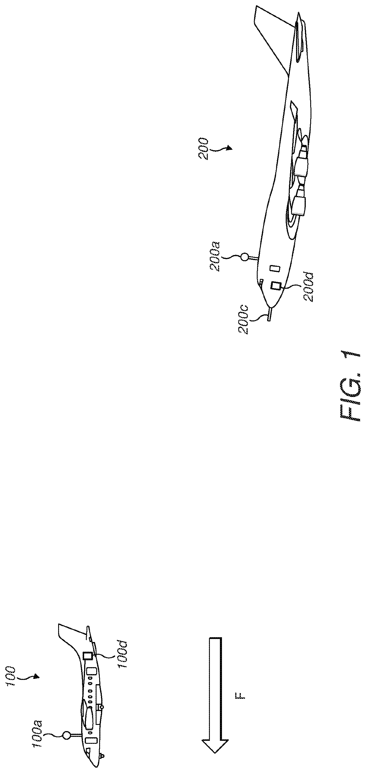
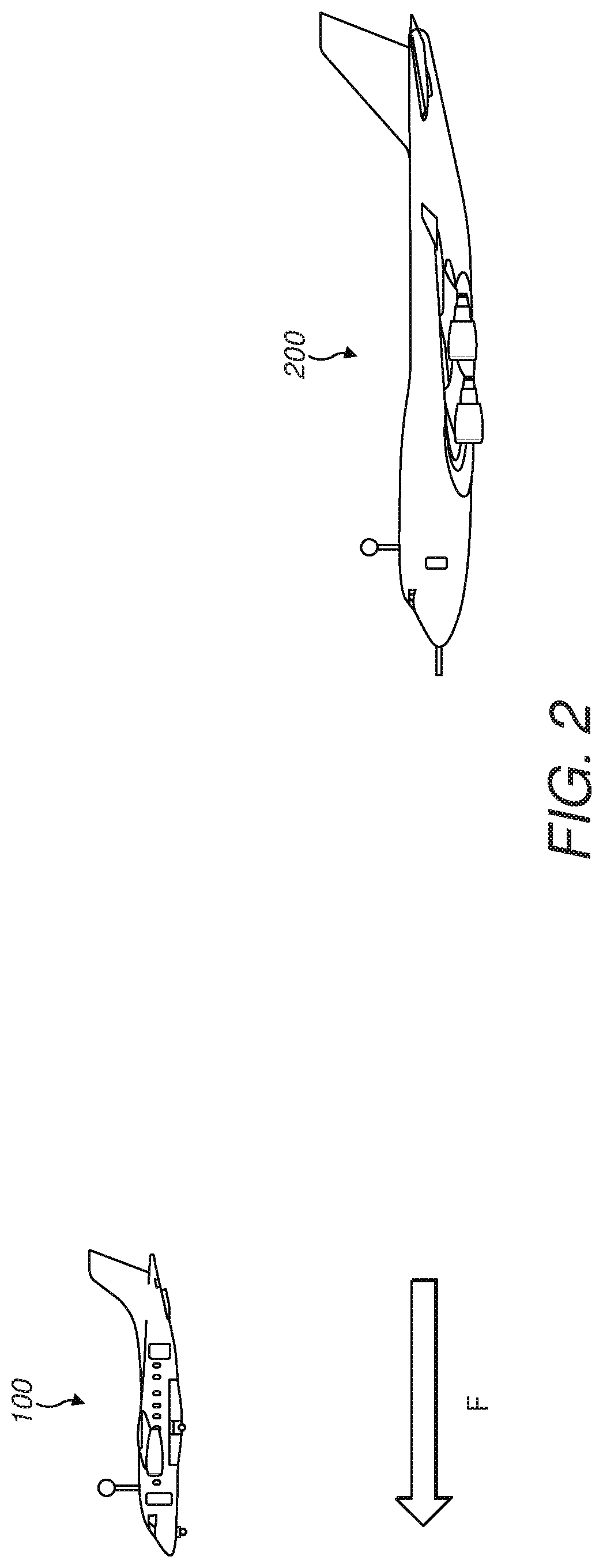
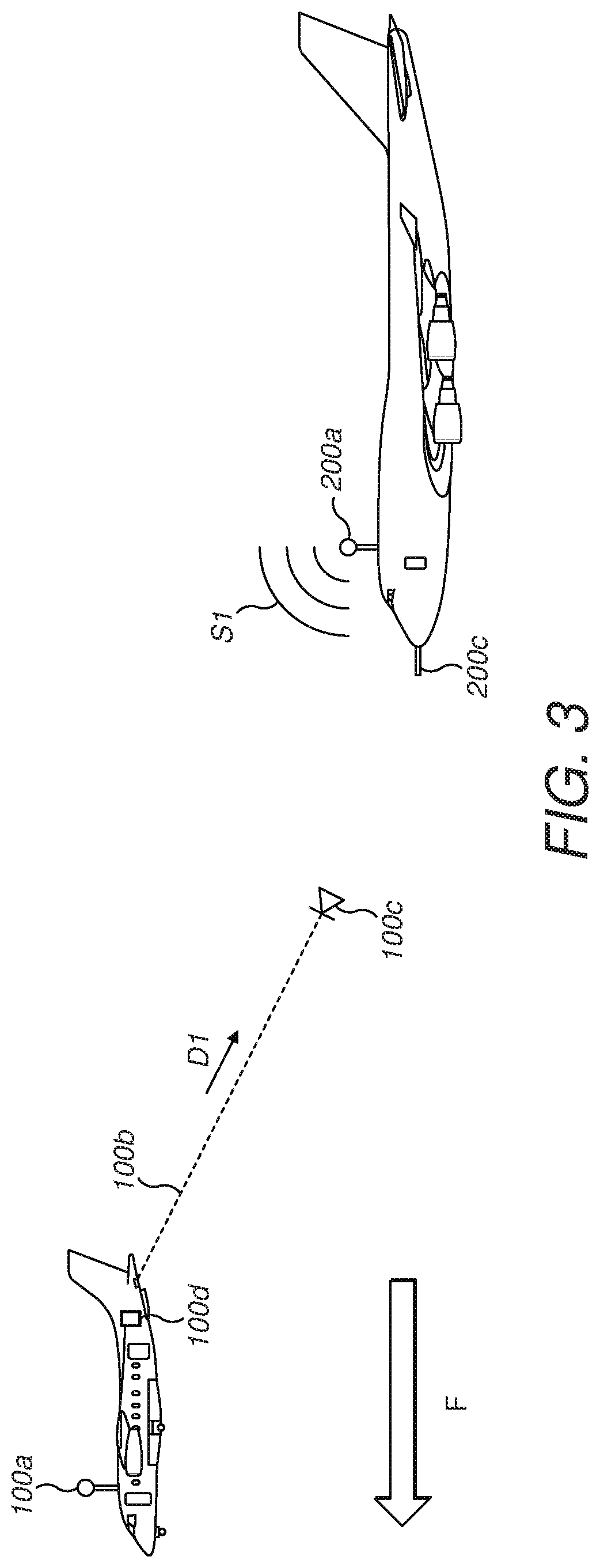
[0060]FIG. 1 shows a receiver aircraft 100, which is a commercial airliner. The receiver aircraft 100 is flying straight and level in a forward direction F at a constant speed. In other words, the receiver aircraft 100 is being flown at a steady cruise.

[0061]The receiver aircraft 100 comprises a communication unit (e.g. including an antenna) 100a. The receiver aircraft 100 further comprises a cable drum unit (not shown in the Figures) which is located in the tail section of the aircraft 100. In this example the drum is a motorised, multi-speed, geared drum which is articulated such that it can be disposed in any orientation relative to the direction of travel of the receiver aircraft 100. The cable drum unit houses a cable 100b (not shown in FIG. 1) which is wound around the drum, one end of the cable 100b being fixedly attached to the drum. In this example the cable 100b is constructed from steel. Alternatively the cable 100b may be constructed from some other material having high ...


PUM


Abstract

A method of operating a supply aircraft for in-flight recharging comprises: transmitting a deploy command signal from a communication unit of the supply aircraft to a communication unit of a receiver aircraft, to cause a line and drogue to deploy from the receiver aircraft; controlling at least one of the supply aircraft and the drogue to engage the drogue with a first end of an electrical cable of the supply aircraft, a second end of the electrical cable being connected to the supply aircraft; and transmitting a return command signal from the communication unit of the supply aircraft to the communication unit of the receiver aircraft, to cause the line and drogue to return to the receiver aircraft with the first end of the electrical cable. The supply aircraft is located behind the receiver aircraft and the deploy command signal is for causing the line and drogue to deploy rearwardly of the receiver aircraft.

Description

BACKGROUND OF THE INVENTION[0001]The present invention relates to methods and systems for in-flight (re)charging of aircraft.[0002]In-flight refueling (IFR) involves the transfer of fuel (typically a liquid fuel, e,g, kerosene) from one aircraft (the “tanker”) to another aircraft (the “receiver”) during flight. IFR (also known as aerial refueling or air-to-air refueling) has become a well-established methodology used to extend the range or loiter time (or increase take-off payload) of military aircraft. Typically the tanker is based on an airliner which has been specially redesigned or converted for refueling operations, while the receiver is usually a fighter aircraft, or possibly a bomber or reconnaissance aircraft.[0003]Experimentation with IFR began in the 1920s and continued through the 1930s. Early systems used a grappling method, whereby the crew of a supply aircraft would unreel a fuel hose from the tanker and the crew of a receiver aircraft would grapple the hose in the air...

Claims


Application Information

Patent Timeline
Patent Type & Authority Applications(United States)
IPC IPC(8): B64D39/02B64D39/06H02J7/00H02J50/10
CPCB64D39/02B64D39/06H02J50/10H02J7/00032H02J7/0045B64D39/00B64U50/34
Inventor PITMAN, JAMES
Owner BRULIC LTD
Why Eureka
Try Eureka