Digital broadcast receiving device and related receiving method

a receiving device and digital broadcast technology, applied in the field of digital broadcasting, can solve problems such as user perception of latency, and achieve the effects of reducing channel switching latency, improving user experience, and effective alleviation of channel switching latency

Active Publication Date: 2021-12-09
REALTEK SEMICON CORP
View PDF4 Cites 0 Cited by
  • Summary
  • Abstract
  • Description
  • Claims
  • Application Information

AI Technical Summary

Benefits of technology

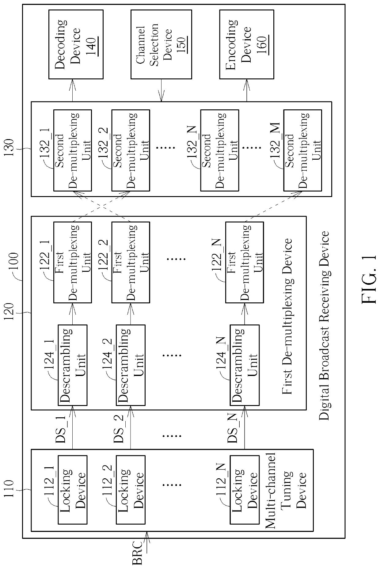
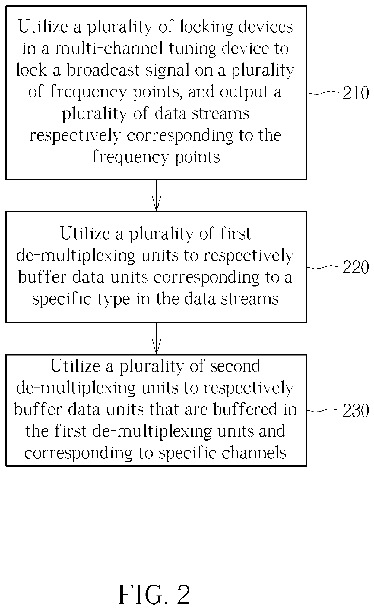
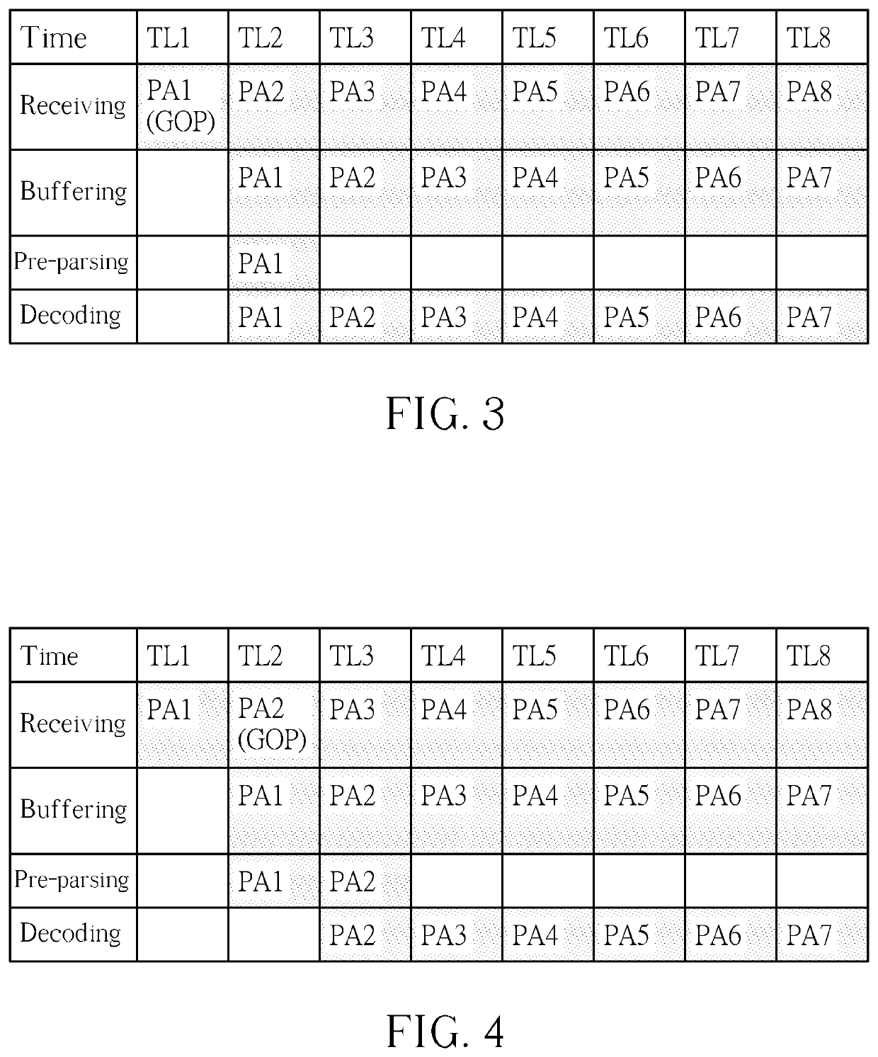
[0004]In order to reduce the latency of channel switching and improve user experience, the present invention provides innovative digital broadcast receiver architecture. Specifically, the present invention uses a multi-channel tuning device with multiple frequency point locking capabilities, thereby to simultaneously lock multiple frequency points in a broadcast signal, where the multiple frequency points may correspond to a channel that is currently being watched by the user and several channels that are previously watched before and / or about to be watched later. Therefore, the multi-channel tuning device can pre-lock those channels the user may watch later, thereby pre-obtaining data units corresponding to a variety of channels. In addition, the present invention uses multiple de-multiplexing units to properly filter and de-multiplex the data units. First, data units that are not associated with video / audio information are filtered out through a first set of de-multiplexing units. Second, data units that correspond to different channels are respectively buffered by a second set of de-multiplexing units. Once the user issues a channel switching command, a decoding device can immediately obtain data units of the selected channel through the second set of de-multiplexing units and decode video / audio to reproduce channel contents. In this regards, the latency of channel switching can be effectively alleviated, achieving fast channel change (FCC).

Problems solved by technology

Each time the user switches to a new channel, the above process needs to be repeated, which brings a perceivable latency to the user.

Method used


Image

  • Digital broadcast receiving device and related receiving method
  • Digital broadcast receiving device and related receiving method
  • Digital broadcast receiving device and related receiving method

Examples


Embodiment Construction

[0012]In the following, numerous specific details are described to provide a thorough understanding of embodiments of the present invention. However, one of skilled in the art will understand how to implement the present invention in the absence of one or more specific details, or relying on other methods, elements or materials. In other instances, well-known structures, materials or operations are not shown or described in detail in order to avoid obscuring the main concepts of the present invention.

[0013]Reference throughout this specification to “one embodiment”, “an embodiment”, “one example” or “an example” means that a particular feature, structure or characteristic described in connection with the embodiment or example is included in at least one embodiment of the present embodiments. Thus, appearances of the phrases “in one embodiment”, “in an embodiment”, “one example” or “an example” in various places throughout this specification are not necessarily all referring to the s...


PUM


Abstract

A digital broadcast receiving device includes a multi-channel tuning device, a first de-multiplexing device, a second de-multiplexing device. The multi-channel tuning device includes a plurality of locking devices, wherein the locking devices are arranged to lock a broadcast signal at a plurality of frequency points, and respectively output a plurality of data streams that correspond to the frequency points. The first de-multiplexing device includes a plurality of first de-multiplexing units, wherein the first de-multiplexing units are respectively associated with one of the locking devices and arranged to respectively buffer data units in the data streams that correspond to specific types. The second de-multiplexing device is coupled to the first de-multiplexing device and includes a plurality of second de-multiplexing units, wherein the second de-multiplexing units are arranged to respectively buffer data units that are buffered by the first de-multiplexing units and correspond to specific channels.

Description

CROSS REFERENCE TO RELATED APPLICATIONS[0001]This application claims the benefit of U.S. Provisional Application No. 62 / 704,950, filed on Jun. 4, 2020. The entire contents of the related applications are incorporated herein by reference.BACKGROUND OF THE INVENTION1. Field of the Invention[0002]The present invention relates to digital broadcasting, and more particularly, to receiving devices and related methods with multiple frequency points locking, de-multiplexing and buffering functions.2. Description of the Prior Art[0003]Typically, a digital broadcasting receiver receives signals in a wide frequency band (i.e., contents from various broadcasting channels) and accordingly controls a tuner in the receiver in accordance with a channel selected by the user to synchronize with a frequency of the selected channel, thereby to lock the frequency. After the signal is stable, a de-multiplexer in the receiver de-multiplexes data received in the locked signal, and a decoder decodes the data...

Claims


Application Information

Patent Timeline
Patent Type & Authority Applications(United States)
IPC IPC(8): H04N21/434H04N21/44H04N21/438H04N5/455
CPCH04N21/4347H04N21/44004H04N21/4348H04N5/455H04N21/4383H04N21/4384H04N21/4263H04N21/42615
Inventor CHEN, CHUN-YI
Owner REALTEK SEMICON CORP
Why Eureka
Try Eureka