
Method for operating a radar sensor in a motor vehicle

Pending Publication Date: 2021-12-30
ROBERT BOSCH GMBH
View PDF34 Cites 0 Cited by
  • Summary
  • Abstract
  • Description
  • Claims
  • Application Information

AI Technical Summary

Benefits of technology

The present invention is about a radar system that can be easily set up for a wide range of tasks. It can measure with high accuracy and can handle dynamic situations with a high time resolution. This means that the system can perform multiple tasks with a single radar sensor, increasing its functionality while avoiding interferences between signals. This results in a cost-effective and efficient solution.

Problems solved by technology

Since the angular resolution is dependent on the size of the aperture and therefore the length of the trajectory driven through in a measuring cycle, which for its part, is proportional to the product of driving speed and time, the time resolution in the case of a SAR evaluation with high angular resolution is inevitably limited.

Method used


Image

  • Method for operating a radar sensor in a motor vehicle
  • Method for operating a radar sensor in a motor vehicle
  • Method for operating a radar sensor in a motor vehicle

Examples


Embodiment Construction

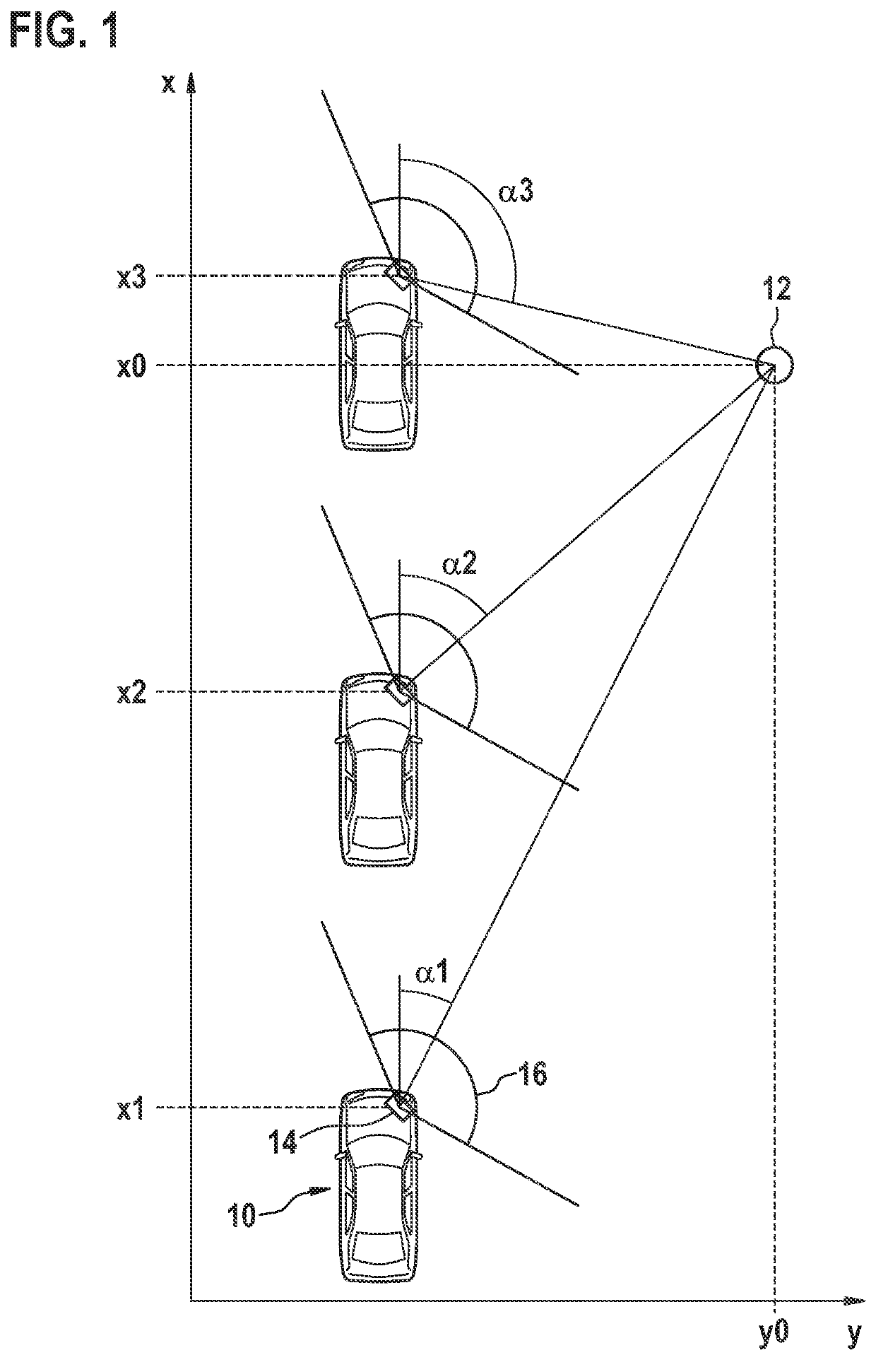
[0029]FIG. 1, in a Cartesian coordinate system having axes x and y, shows a motor vehicle 10, which is traveling with constant speed in the direction of axis x, at three different points in time, at which in each case it occupies a different position x1, x2, x3 along the x axis. A stationary object 12 is located in a coordinate position (x0, y0) laterally alongside the trajectory traveled by vehicle 10. Front right, vehicle 10 has a radar sensor 14, represented only schematically here, whose locating-angle range 16 covers both the area in front of vehicle 10 as well as the area laterally alongside the vehicle in the direction of axis y. (A sensor disposed in mirror-image to it on the other side of the vehicle is not shown here.)

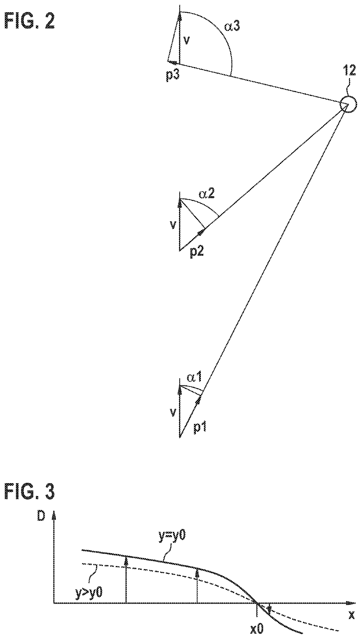
[0030]Object 12 is located by radar sensor 14 at each of positions x1, x2, x3 at a different locating angle α1, α2, α3. Locating angles α1-α3 are defined in each case as the angle between the line of sight from radar sensor 14 to object 12 and the forward dir...


PUM


Abstract

A method for operating a radar sensor in a motor vehicle, in which in a SAR measuring mode according to the principle of the synthetic aperture, objects, including stationary objects, are located with high angular resolution. The same radar sensor is operated in time-shifted manner or concurrently in the SAR measuring mode and in a Doppler measuring mode, the relative speeds of objects, including moving objects, being measured with a time resolution in the Doppler measuring mode that is greater than the time resolution in the SAR measuring mode.

Description

CROSS REFERENCE[0001]The present application claims the benefit under 35 U.S.C. § 119 of German Patent Application No. DE 102020207879.3 filed on Jun. 25, 2020, which is expressly incorporated herein by reference in its entirety.FIELD[0002]The present invention relates to a method for operating a radar sensor in a motor vehicle, in which in a SAR (synthetic aperture radar) measuring mode according to the principle of the synthetic aperture, objects, including stationary objects, are located with high angular resolution.BACKGROUND INFORMATION[0003]Radar systems for measuring distances, relative speeds and locating angles of objects are used in motor vehicles for various assistance functions, for example, for safety functions such as automatic collision warning or collision avoidance, as well as for convenience functions like an automatic search for parking spaces, for instance. One example for a method for operating a SAR radar sensor in a motor vehicle is described in German Patent ...

Claims


Application Information

Patent Timeline
IPC IPC(8): G01S13/90G01S13/58G01S13/931
CPCG01S13/9029G01S13/931G01S13/58G01S13/9017G01S13/90G01S13/583B60R11/00B60R2011/008G01S13/9041G01S13/584G01S2013/0272G01S13/60G01S13/524G01S7/40G01S13/34G01S2013/9327
Inventor SCHINDLER, DANIELHAKOBYAN, GORFINK, JOHANNESPENSKE, KAISCHOOR, MICHAELHIMMELSTOSS, ARMIN
Owner ROBERT BOSCH GMBH
Learn More