Supercharge Your Innovation With Domain-Expert AI Agents!

Camera system with a plurality of image sensors

a camera system and image sensor technology, applied in the field of camera systems with a plurality of image sensors, can solve the problems of limited angle of view of cameras, affecting the quality of images, and cutting on the sides of images,

Pending Publication Date: 2021-12-30
LABLANS PETER
View PDF0 Cites 3 Cited by
  • Summary
  • Abstract
  • Description
  • Claims
  • Application Information

AI Technical Summary

Benefits of technology

The present invention provides methods and systems for recording, processing, and displaying multiple images simultaneously in a panoramic format. The invention includes a camera system with multiple cameras fixed in a single body, each with a lens and image sensor. The image sensors are rotationally aligned with a small misalignment angle, and a controller reads image data from the active areas of the cameras. The memory stores raw image data from the cameras, and the screen displays a panoramic video image based on the registered raw image. The invention also includes a camera system with a registered raw image that has alignment errors of less than 10 pixels. Additionally, the invention includes a camera that can be part of a mobile phone or computer tablet.

Problems solved by technology

Videos, especially recorded by smartphones, are hampered by a limited angle-of-view of cameras.
This leads to images that are limited in view, often cut on the sides and are unable to adequately fill a display.
Images of scenes may lose context of the environment wherein a scene takes place.
This limits the ability to watch and / or review of panoramic images in real-time.
However, stitching on images is commonly time consuming and is difficult to do in real-time.

Method used


Image

  • Camera system with a plurality of image sensors
  • Camera system with a plurality of image sensors
  • Camera system with a plurality of image sensors

Examples


first embodiment

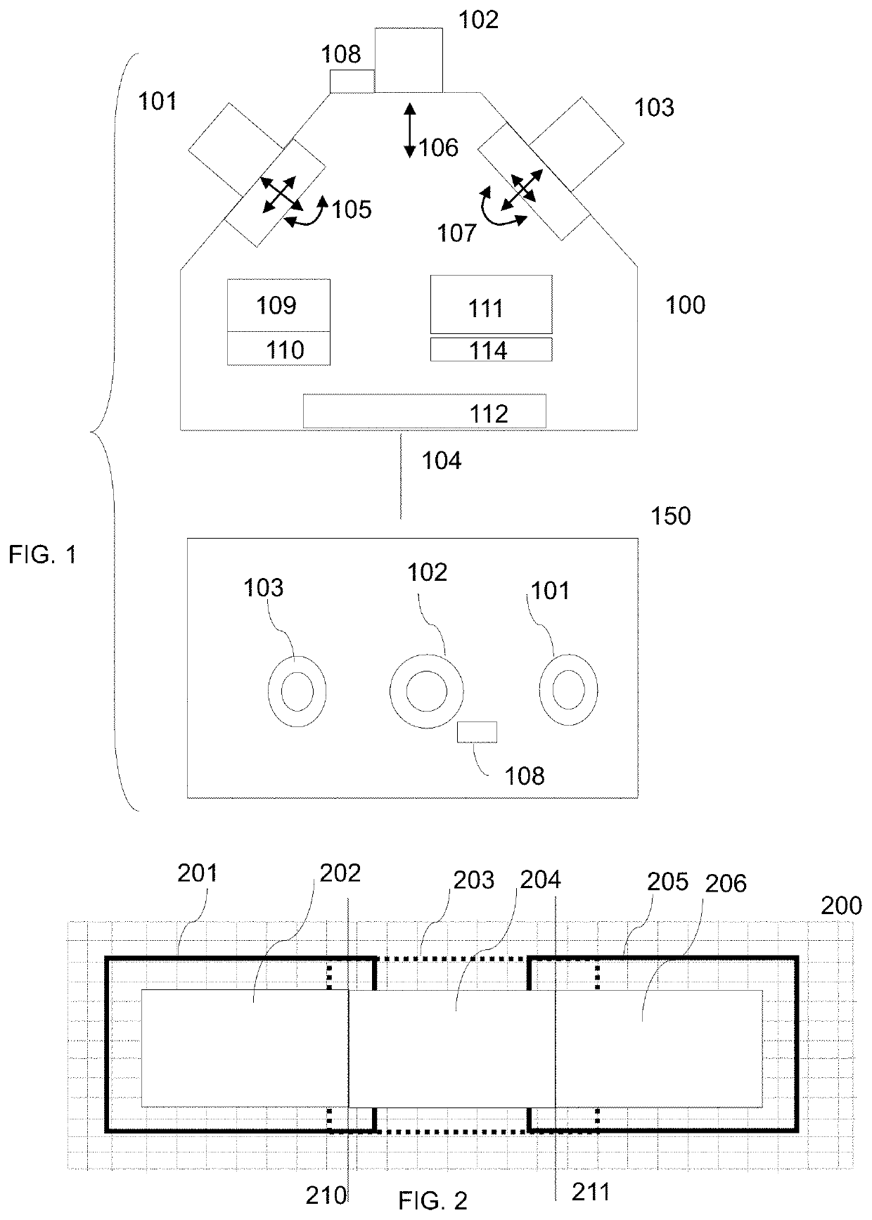
[0083]In a first embodiment, a user may select if images from a single lens or of all three lenses will be recorded. If the user selects recording images from all three lenses, then via the camera controller a control signal may be provided that focuses all three lenses on a scene. Calibrated software may be used to ensure that the three lenses and their control motors are focused correctly. In a further embodiment, the image signals are transmitted to the memory or data storage unit 1112 for storing the video or still images.

[0084]In yet a further embodiment, the signals from the three lenses may be first processed by the processor 1113 to be registered correctly into a potentially contiguous image formed by 3 images that can be displayed in a contiguous way. The processor in a further embodiment may form a registered image from 3 images that may be displayed on a single display.

[0085]The processor in yet a further embodiment may also process the images so that they are registered ...

second embodiment

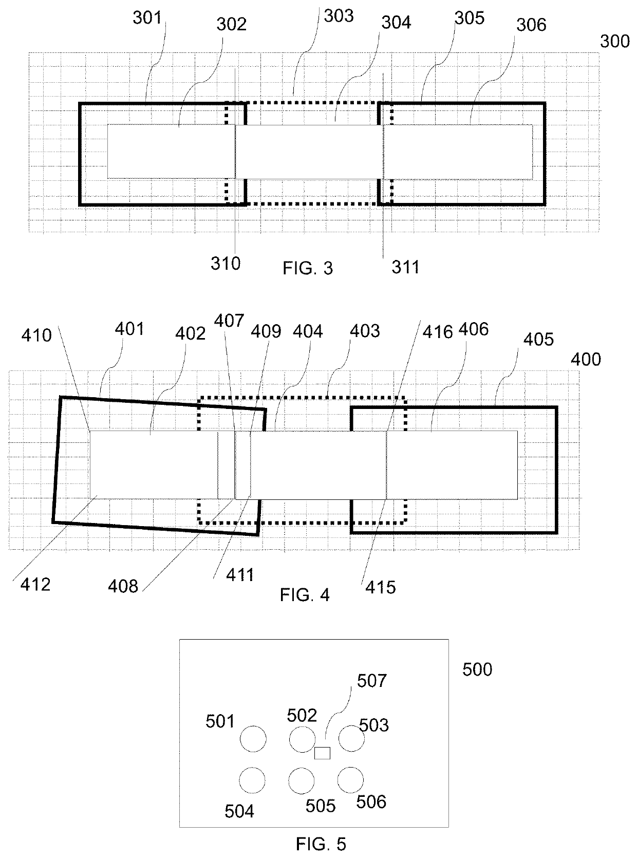
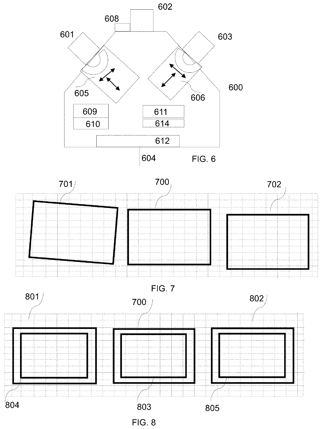
[0116]In one embodiment of the present invention, all images are recorded at substantially the same time. In a second embodiment, at least two images may be taken at substantially not the same time.

[0117]In a further embodiment, a camera has 3 or more lenses, each lens being associated with an image sensor. Each lens may be a zoom lens. All lenses may be in a relatively fixed position in a camera body. In such a construction, a lens may focus, and it may zoom, however, it has in all other ways a fixed position in relation to a reference position of the camera. As an illustrative example, lenses are provided in a camera that may be aligned in one line. Such an arrangement is not a required limitation. Lenses may be arranged in any arrangement. For instance 3 lenses may be arranged in a triangle. Multiple lenses may also be arranged in a rectangle, a square, or an array, or a circle, or any arrangement that may provide a stitched image as desired. The calibration of lenses and sensor ...


PUM


Abstract

Active areas of image sensors are determined by one or more parameters defining a mergeline or memory addresses where image data is stored. Image data generated by active areas of different image sensors are combined to create a panoramic image. Image distortion is detected in image data generated by an active area of an image sensor. Distortion in image data is addressed by configured image processing instructions. A group of one or more processors is assigned to at least each image sensor. At least one set of instructions assures that image data generated by different image sensors creates a combined image of a video with a substantially seamless transition between areas. Curved image sensors limit distortion. Cameras are fixedly held in a calibrated body.

Description

STATEMENT OF RELATED CASES[0001]This application claims the benefit and is a continuation-in-part of U.S. Non-provisional patent application Ser. No. 16 / 814,719 filed on Mar. 10, 2020. Application Ser. No. 16 / 814,719 claims the benefit and is a continuation-in-part of U.S. Non-provisional patent application Ser. No. 16 / 011,319 filed on Jun. 30, 2018. Application Ser. No. 16 / 011,319 claims the benefit and is a continuation-in-part of U.S. Non-provisional patent application Ser. No. 15 / 836,815 filed on Dec. 8, 2017. Patent application Ser. No. 15 / 836,815 is a continuation and claims the benefit of U.S. Non-provisional patent application Ser. No. 12 / 983,168 filed on Dec. 31, 2010. Patent application Ser. No. 12 / 983,168 claims the benefit of U.S. Provisional Patent Application Ser. No. 61 / 365,347, filed Jul. 18, 2010, and of U.S. Provisional Patent Application Ser. No. 61 / 322,875, filed Apr. 11, 2010 and of U.S. Provisional Patent Application Ser. No. 61 / 291,861, filed Jan. 1, 2010. Pat...

Claims


Application Information

Patent Timeline
Patent Type & Authority Applications(United States)
IPC IPC(8): G03B35/00H04N13/246H04N5/232H04N5/262H04N13/239
CPCG03B35/00H04N13/246H04N5/23238H04M1/72409H04N13/239H04M2250/16H04N5/2624G03B37/04H04M1/0264H04N13/243H04M1/72403H04M2250/52G03B35/08H04N13/296H04N23/45H04N23/58H04N23/698H04N23/63H04N23/69H04N23/90H04M1/72412
Inventor LABLANS, PETER
Owner LABLANS PETER
Features
  • R&D
  • Intellectual Property
  • Life Sciences
  • Materials
  • Tech Scout
  • Unparalleled Data Quality
  • Higher Quality Content
  • 60% Fewer Hallucinations
Learn More