

Blood Pump Or Balloon Cycling And Venous Occlusion
a technology of venous occlusion and blood pump, which is applied in the direction of balloon catheters, other medical devices, catheters, etc., can solve the problems of prolonged hospital stay and/or ineffective decongestion, acute and/or chronic renal failure, and inability to effectively decongest, etc., to improve filtration gradient, improve renal performance, and reduce the pressure of the inferior vena cava
- Summary
- Abstract
- Description
- Claims
- Application Information
AI Technical Summary
Benefits of technology
Problems solved by technology
Method used
Image

Examples
second embodiment
[0044]FIG. 7 describes the renal perfusion enhancement device 121 which comprises a single catheter 123 having an inflation lumen 110 placed within an outside wall 104 of the catheter 123, and a central lumen 108 disposed within the inflation lumen 110 creating a passageway for a guidewire 114. The guidewire 114 is inserted in the central lumen 108 of the catheter 123 through an opening 112A (e.g., a Touhy-Borst connector) connected to the catheter hub 112 at the proximal end of the catheter 123. A first downstream cycling balloon 106 is positioned at the distal portion of the catheter 123 and a second upstream occlusive balloon 107 is positioned at a proximal direction away from the downstream cycling balloon 106 of the catheter 123. Inflation and deflation of the downstream cycling balloon 106 is accomplished through one or more inflation apertures 116 placed in the inflation lumen 110A inside the downstream cycling balloon 106 and the inflation and deflation of the upstream occlu...
third embodiment
[0048]FIG. 11 describes the renal perfusion enhancement device 131 which comprises a first catheter 133 having an inflation lumen 110 located within an outside wall 104 of the catheter 133, and a central lumen 108 disposed within the inflation lumen 110 creating a passageway for a guidewire 114. The guidewire 114 is inserted in the central lumen 108 of the catheter 133 through an opening 112A (a Touhy-Borst connector) connected to the catheter hub 112 at the proximal end of the catheter 133. A downstream cycling balloon 106 is positioned at the distal portion of the catheter 133. The device 131 further comprises a second catheter 137 having an inflation lumen 137A and an inflation aperture 117A placed within the inflation lumen 137A of the catheter 137. An upstream occlusive balloon 107 is positioned at a distal end of the catheter 137. Inflation and deflation of the downstream cycling balloon 106 is accomplished through the inflation aperture 116 connected to the inflation lumen 11...
fourth embodiment
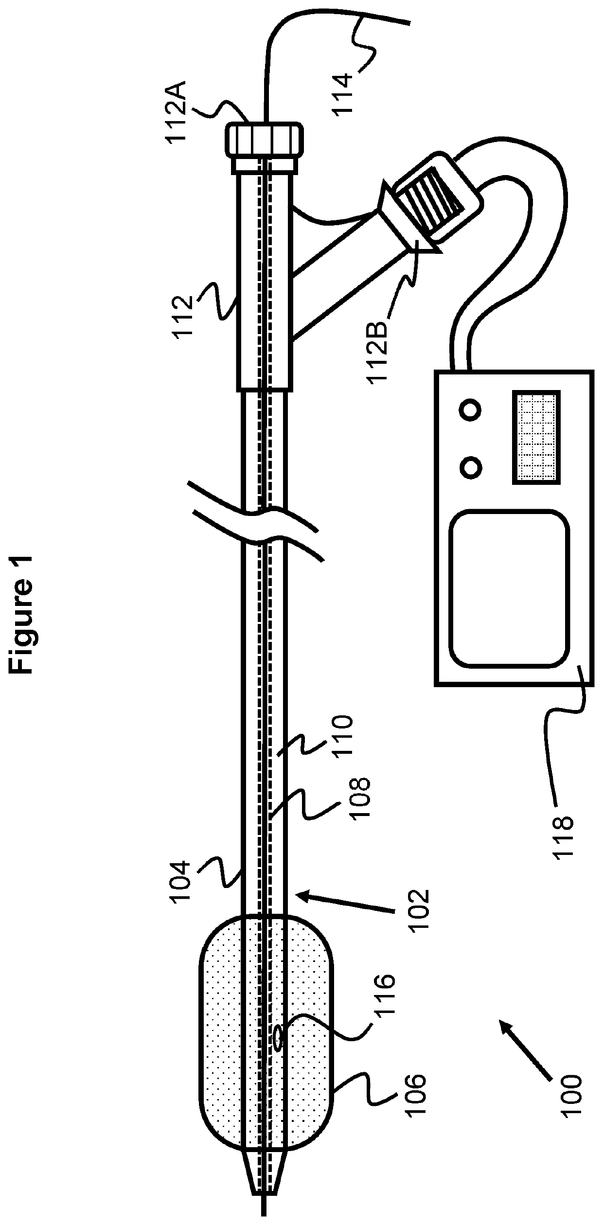
[0051]FIG. 14 illustrates the renal perfusion enhancement device 140 which comprises a first catheter 102 having an inflation lumen 110 placed within an outside wall 104 of the catheter 102, and a central lumen 108 disposed within the inflation lumen 110 creating a passageway for a guidewire 114. The guidewire 114 is inserted in the central lumen 108 of the catheter 102 through an opening 112A (e.g., a Touhy-Borst connector) connected to the catheter hub 112 at the proximal end of the catheter 102. A downstream cycling balloon 106 is positioned at the distal portion of the catheter 102. The device 140 further comprises a second catheter 142 having an outer catheter wall 144 forming an inflation lumen 143 and an inflation aperture 117B connected to the inflation lumen 143 of the catheter 142. The catheter 142 can be delivered through an access sheath (not shown in the drawings) into the vena cava 12 of the patient. An upstream occlusive balloon 107 is positioned at a distal end of th...
PUM
 Abstract
Description
Claims
Application Information