
3-d printer

a 3d printer and printer technology, applied in the field of 3d printers, can solve the problems of reducing productivity, slowing and/or halting the printing process, and photopolymer adhesion, so as to limit and/or prevent the adhesion of photopolymer and draw heat out of the tank

Active Publication Date: 2022-01-06
NISSAN NORTH AMERICA
View PDF3 Cites 0 Cited by
  • Summary
  • Abstract
  • Description
  • Claims
  • Application Information

AI Technical Summary

Benefits of technology

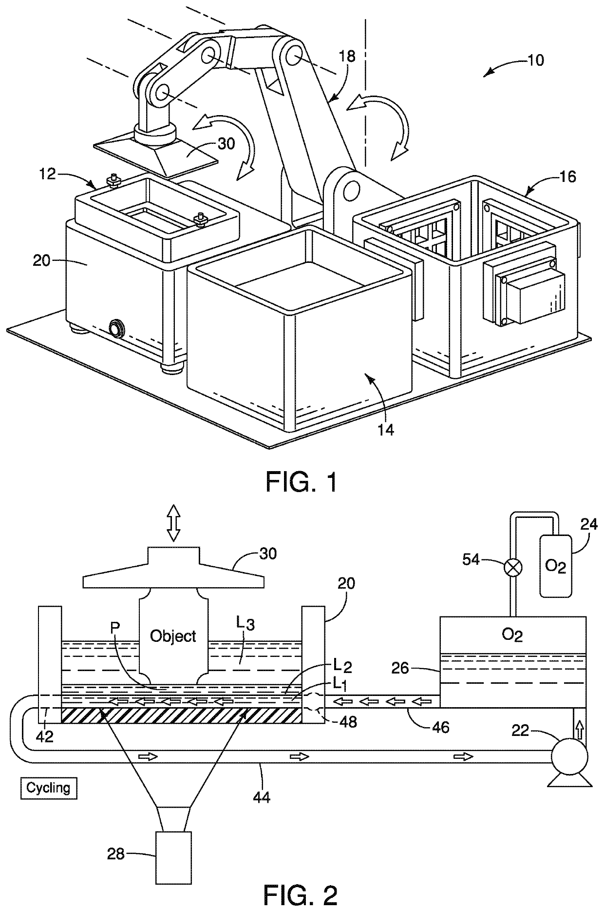
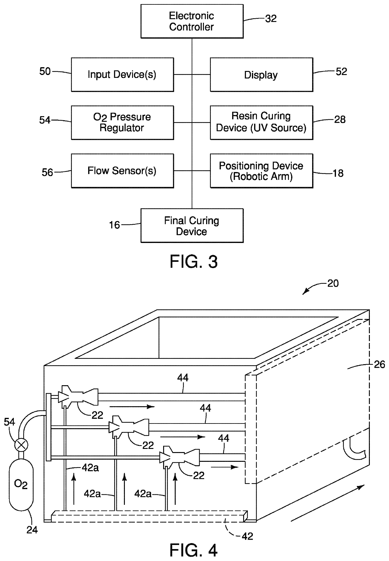
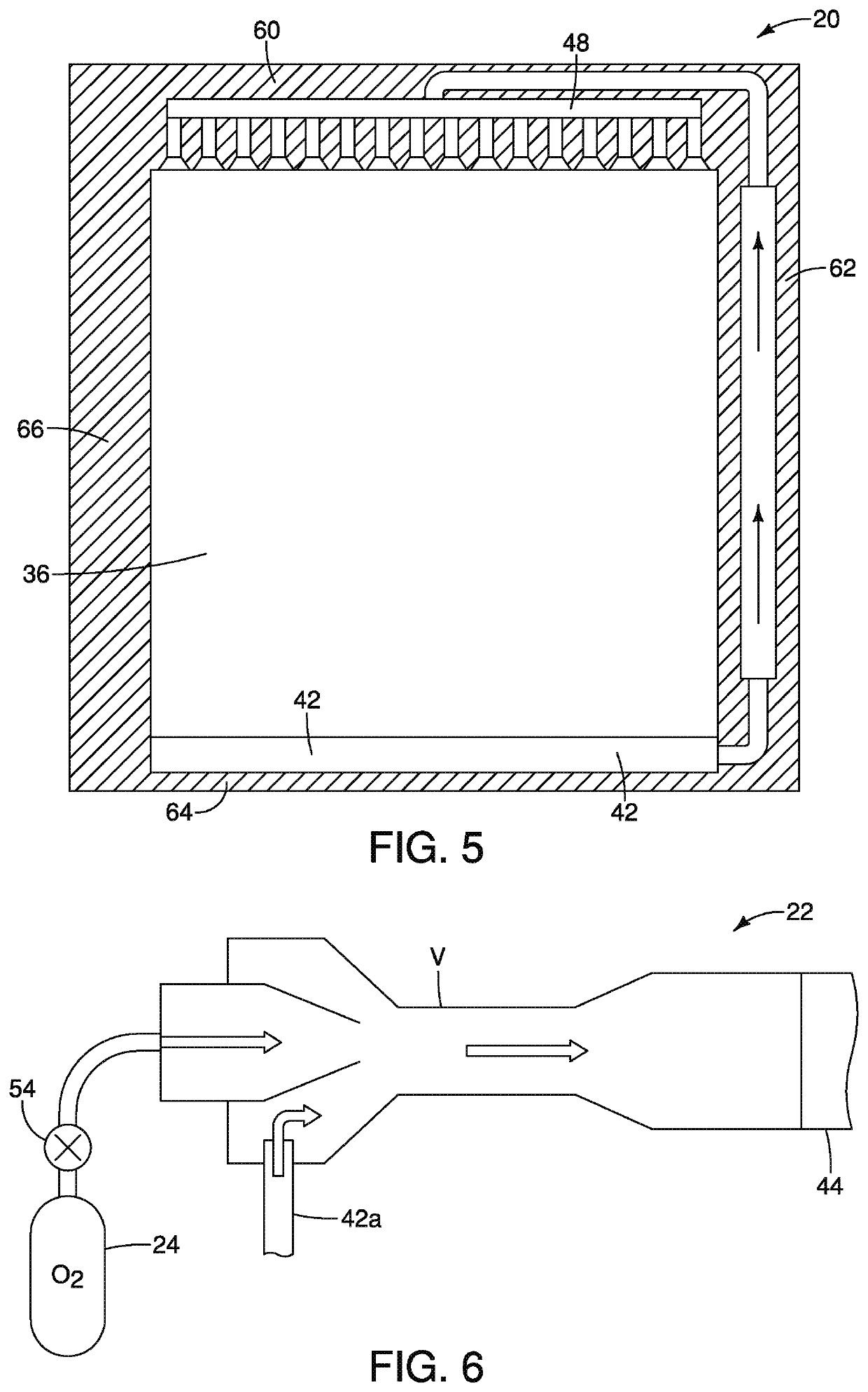
The technical effect of this patent is to create a continuous flow of liquid along the surface of a bottom wall, which prevents the photopolymer from sticking to the wall and draws heat out of the tank.

Problems solved by technology

One problem with this arrangement, is that portions of the photopolymer can adhere to the transparent substrate (bottom wall of the tank).
This adhesion slows and / or delays the printing process. thereby decreasing productivity.

Method used


Image

  • 3-d printer
  • 3-d printer
  • 3-d printer

Examples


second embodiment

[0069]Referring now to FIG. 15, a modification to the tank 20 in accordance with a second embodiment will now be explained. In view of the similarity between the first and second embodiments, the parts of the second embodiment that are identical to the parts of the first embodiment will be given the same reference numerals as the parts of the first embodiment. Moreover, the descriptions of the parts of the second embodiment that are identical to the parts of the first embodiment may be omitted for the sake of brevity. The parts of the second embodiment that differ from the parts of the first embodiment will be indicated with a single prime (′).

[0070]In the second embodiment, the bottom wall 36 of the first embodiment is replaced with a bottom wall 36′. The bottom wall 36′ includes a plurality of micro-openings or micro holes that allow forced oxygen O2 to be fed into the gas permeable liquid L1 (the first mobile layer) as is flows through the tank 20, to further increase the amount ...


PUM

PropertyMeasurementUnit
sizeaaaaaaaaaa
areaaaaaaaaaaa
permeableaaaaaaaaaa

Abstract

A method of operating a 3-D printer apparatus includes a tank structure with a bottom wall with a printing area defined above and spaced apart from the bottom wall. A gas permeable liquid within the tank overlays the bottom wall of the tank structure defining a first mobile layer below the printing area. An inhibition liquid within the tank overlays the gas permeable liquid defining a second mobile layer below the printing area. A polymerizable resin overlays the inhibition liquid and flows into the printing area. Positioning of an object carrier controlled such that a lower surface of the object carrier is initially located within the polymerizable resin and within the printing area. Operation of a resin curing device beneath the bottom wall provides light to the printing area polymerizing predetermined portions of the polymerizable resin forming an object attached to the lower surface of the object carrier.

Description

BACKGROUNDField of the Invention[0001]The present invention generally relates to three dimension printers (3-D printers). More specifically, the present invention relates to 3-D printer that includes a printing tank configured to employ two different liquid mobile layers that are located below a photopolymer that is cured to form an object during the printing process.Background Information[0002]Three dimension printings (3-D printers) have been used to form a wide variety of products. Objects are printed layer by layer by the 3-D printer by curing portions of a photopolymer layer by layer, one layer at a time, within a tank filled with the photopolymer. A curing device, such as an ultraviolet light source, is projected through a transparent substrate or bottom wall of the tank in order to cure each layer of the object on a carrier surface that is at least partially submerged within the photopolymer. The carrier surface is incrementally raised upward as each layer is cured thereon. O...

Claims


Application Information

Patent Timeline
Patent Type & Authority Applications(United States)
IPC IPC(8): B29C64/245B33Y30/00B29C64/135B29C64/255B29C64/264B33Y10/00B33Y40/00
CPCB29C64/245B33Y30/00B29C64/135B33Y40/00B29C64/264B33Y10/00B29C64/255B29C64/364B29C64/124B33Y70/00
Inventor ZHAO, NANZHUCAO, JINWEIDALE, NILESHPATIL, SANDEEPGUMECI, CENKABDUL JABBAR, MOHAMMED HUSSAIN
Owner NISSAN NORTH AMERICA
Learn More