
Electronic equipment having heat-dissipating device and method

a technology of heat dissipation device and electronic equipment, which is applied in the direction of electrical apparatus casing/cabinet/drawer, cooling/ventilation/heating modification, instruments, etc., can solve the problems of heat generated by the heat source, problems, and important issues, and achieve the effect of speeding up heat convection

Active Publication Date: 2012-11-27
HANNSTAR DISPLAY CORPORATION
View PDF4 Cites 0 Cited by
  • Summary
  • Abstract
  • Description
  • Claims
  • Application Information

AI Technical Summary

Benefits of technology

[0007]The object of the present invention is to provide an electronic equipment having a heat-dissipating device and method for improving the heat transfer efficiency inside the electronic equipment on condition that the electronic system of the electronic equipment will not be complicated and energy-saving and ejection-decreasing principles can be met.
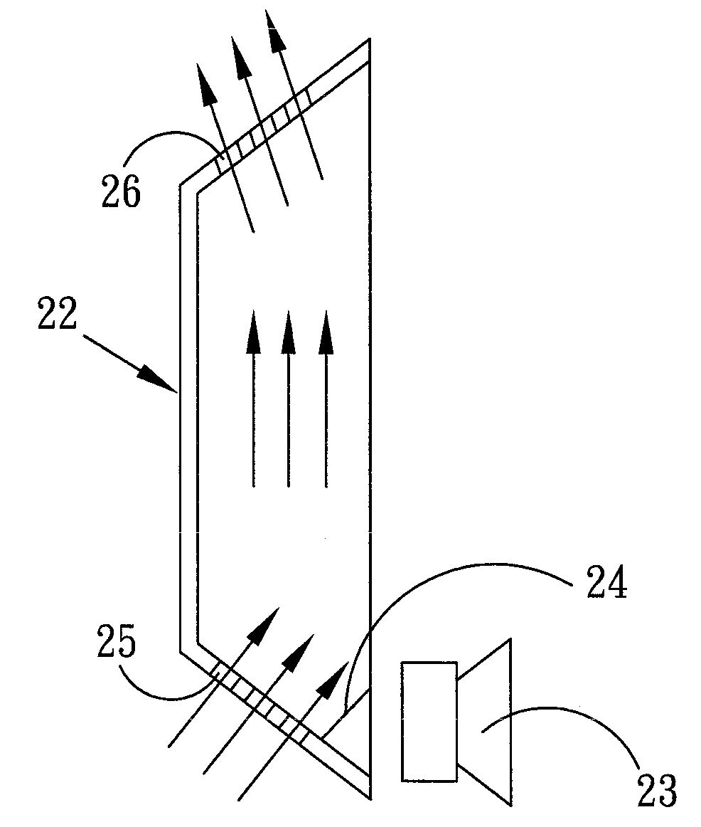
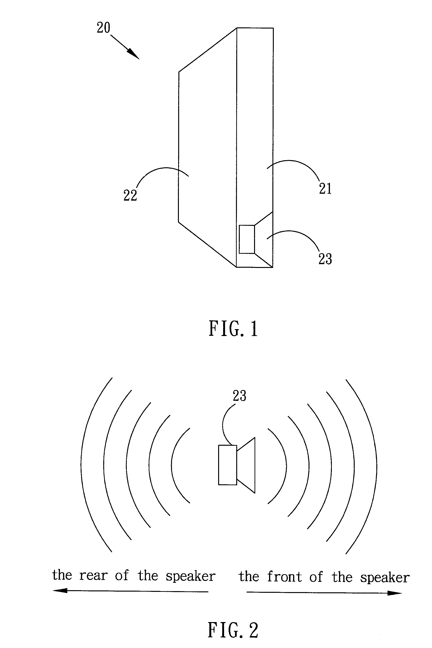
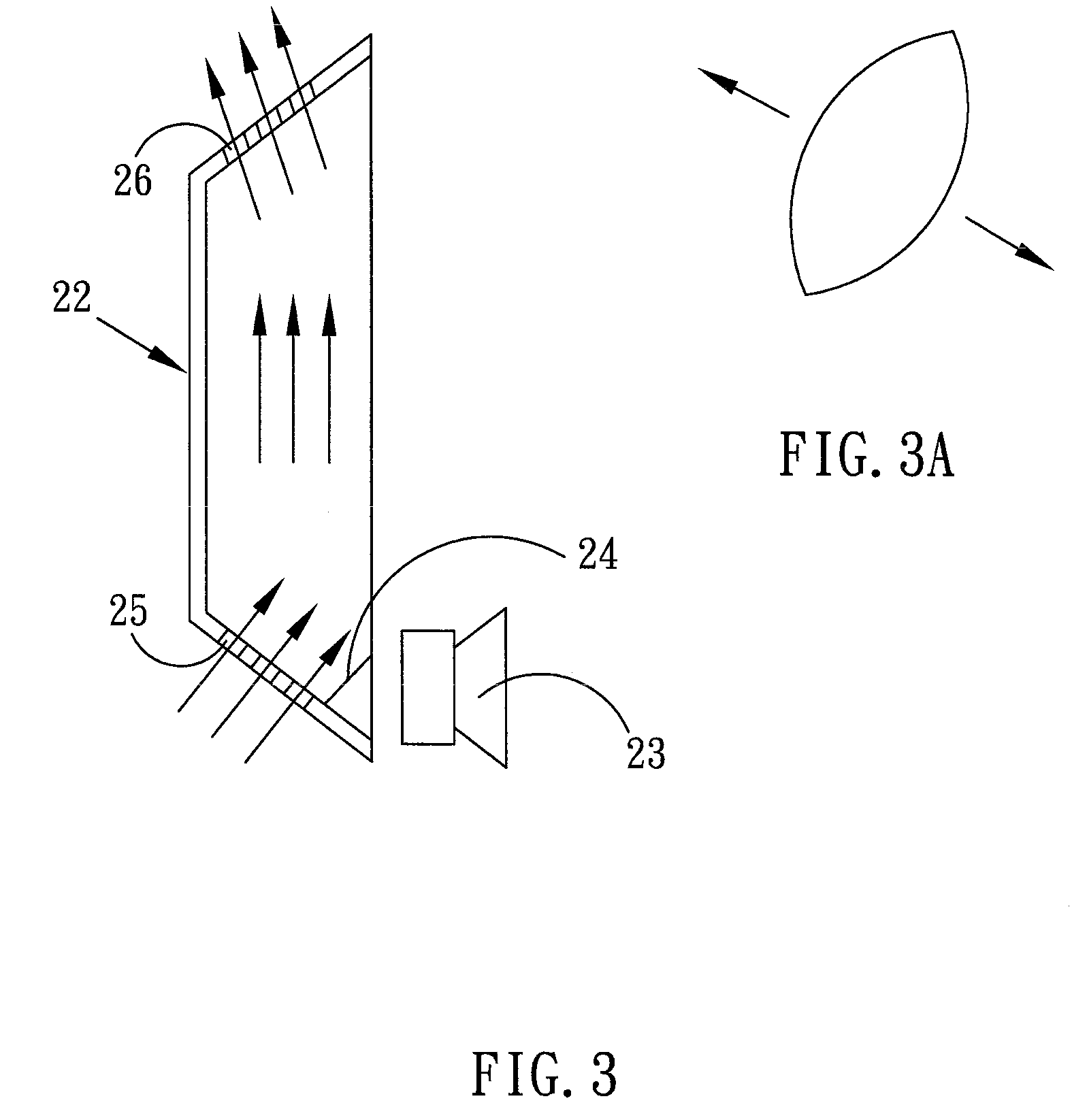
[0008]According to the object, one embodiment of the present invention provides an electronic equipment having a heat-dissipating device, the electronic equipment comprising a housing, a heat source generating heat, a speaker, and at least one vibration component arranged inside the housing, wherein the vibration component receives sound energy emitted by the speaker, causing the vibration component vibrating, thereby speeding up the heat convection and driving out the heat.
[0010]According to the object, one embodiment of the present invention provides a heat-dissipating device applied to a Liquid Crystal Display, which comprises a backlight comprising a plurality of light sources, a display panel, at least one speaker, and at least one vibration film or at least one vibration blade arranged inside the backlight, wherein the vibration film or the vibration blade receives sound energy emitted by the speaker, causing the vibration film or the vibration blade vibrating, thereby speeding up the heat convection and driving out the heat of the light sources.

Problems solved by technology

The heat dissipation of the backlight is an important issue.
The heat generated by the heat source must be dissipated; otherwise some problems will be encountered.
For meeting the requirement of the design illumination, the inputted electricity power of the Light Emitting Diodes is designed at high level, and thus the unwanted high temperature is also accompanied.
The high temperature shifts the wavelength and weakens the illumination of the emitting light.
Therefore, for Liquid Crystal Display, especially for large size Liquid Crystal Display, the heat dissipation still is a problem must be overcome when designing the backlight and the electronic system.
This heat-dissipating structure has disadvantage that after the Liquid Crystal Panel has been operating a period of time, the heat transfer efficiency will be gradually decayed as a result of the temperature of the air near to the outlet of the heat-dissipating channel approximating to the temperature inside the backlight.
However, if the number of the light sources is too large, for example, a large number of Light Emitting Diodes, or, if the Liquid Crystal Display is operated at summer or at a tropic country or at a closing room, the heat transfer efficiency will be decreased.
Although the above two inventions can increase the heat transfer efficiency, the electronic system of the Liquid Crystal Display has been complicated, and an additional electricity power must be provided to the fan, thus exhausting more energy.

Method used


Image

  • Electronic equipment having heat-dissipating device and method
  • Electronic equipment having heat-dissipating device and method
  • Electronic equipment having heat-dissipating device and method

Examples


Embodiment Construction

[0015]Reference will now be made in detail to specific embodiments of the invention. Examples of these embodiments are illustrated in accompanying drawings. While the invention will be described in conjunction with these specific embodiments, it will be understood that it is not intended to limit the invention to these embodiments. On the contrary, it is intended to cover alternatives, modifications, and equivalents as may be included within the spirit and scope of the invention as defined by the appended claims. In the following description, numerous specific details are set forth in order to provide a through understanding of the present invention. The present invention may be practiced without some or all of these specific details. In other instances, well-known process operations and components are not been described in detail in order not to unnecessarily obscure the present invention. While drawings are illustrated in details, it is appreciated that the quantity of the disclos...


PUM

PropertyMeasurementUnit
power consumptionaaaaaaaaaa
temperatureaaaaaaaaaa
power consumptionaaaaaaaaaa

Abstract

An embodiment of the present invention provides a heat-dissipating device of electronic equipment that comprises a housing, a heat source, a speaker, and a vibration film arranged inside the housing. The vibration film will vibrate when receiving the energy transmitted from the speaker, resulting in that the heat convection is accelerated and the heat generated by the heat source is removed.

Description

FIELD OF THE INVENTION[0001]The present invention relates to electronic equipment, more particularly, to an electronic equipment having heat-dissipating device and method.DESCRIPTION OF THE PRIOR ART[0002]In a Liquid Crystal Display (LCD), a backlight is necessary for providing light to its display panel. The conventional backlight comprises a back cover, a plurality of light sources such as Cold Cathode Fluorescent Lamp (CCFL) or Light Emitting Diode (LED) arranged on the back cover, and a reflector arranged between the back cover and the light sources.[0003]The heat dissipation of the backlight is an important issue. In the field of Liquid Crystal Display, the size of the display panel has been getting bigger and bigger. The greater is the size of the display panel, the greater is the number of the light sources, and therefore the greater is the heat generated by the light sources. The heat generated by the heat source must be dissipated; otherwise some problems will be encountere...

Claims


Application Information

Patent Timeline
Patent Type & Authority Patents(United States)
IPC IPC(8): G02F1/1333H05K7/20
CPCG02F1/133385
Inventor PEI, TING-HANG
Owner HANNSTAR DISPLAY CORPORATION
Learn More