Cathode structure including barrier for preventing metal bridging from heater to emitter

a cathode structure and barrier technology, applied in the direction of discharge tube/lamp details, discharge tube main electrodes, incadescent cooling arrangements, etc., can solve the problems of inability to control the amount of electron beams, and the inability to obtain electron beams, etc., to achieve the effect of suppressing short-circuits and emitted unnecessary thermal electrons

Inactive Publication Date: 2008-08-19
PANASONIC CORP
View PDF15 Cites 0 Cited by
  • Summary
  • Abstract
  • Description
  • Claims
  • Application Information

AI Technical Summary

Benefits of technology

[0019]With the above cathode structure, it is possible to suppress an amount of metal material such as barium reaching a part of the heating wire just exposed from the electric insulating material body and around a position of a surface of the electric insulating material body from which the heating wire leads out. This is because, in comparison with a conventional cathode structure in which a heating wire leads out from a side surface of a electric insulating material body, (i) a distance between the electron-emitting surface and a position from which the heating wire leads out of the electric insulating material body becomes longer, and (ii) the metal material such as barium evaporated from the electron-emitting surface has to turn around a flying direction in order to reach the position from which the heating wire leads out of the electric insulating material body.
[0020]As a result, it is possible to suppress short-circuits between the heating wire and the cathode unit and emission of unnecessary thermal electrons as much as possible, in comparison with the conventional cathode structure.
[0022]With the above cathode structure, it is possible to suppress an amount of metal material such as barium reaching a part of the heating wire just exposed from the electric insulating material body and around a position of a surface of the electric insulating material body from which the heating wire leads out, because the cathode unit is disposed at one of the end surfaces of the columnar electric insulating material body, and the heating wire leads out from a side surface of the electric insulating material body, and the electric insulating material body includes a protrusion disposed on the side surface between a position from which the heating wire leads out and the surface of the cathode unit from which electrons are emitted. The protrusion prevents the metal material such as barium evaporated from the electron-emitting surface from reaching a position from which the heating wire leads out.
[0023]As a result, it is possible to suppress short-circuits between the heating wire and the cathode unit and emission of unnecessary thermal electrons as much as possible, in comparison with the conventional cathode structure.

Problems solved by technology

As a result, a relative potential difference between a G1 electrode (control electrode) and a cathode (pellet) corresponding to the cathode voltage and the image signal voltage cannot be obtained, and the amount of electron beam cannot be controlled.

Method used


Image

  • Cathode structure including barrier for preventing metal bridging from heater to emitter
  • Cathode structure including barrier for preventing metal bridging from heater to emitter
  • Cathode structure including barrier for preventing metal bridging from heater to emitter

Examples


first embodiment

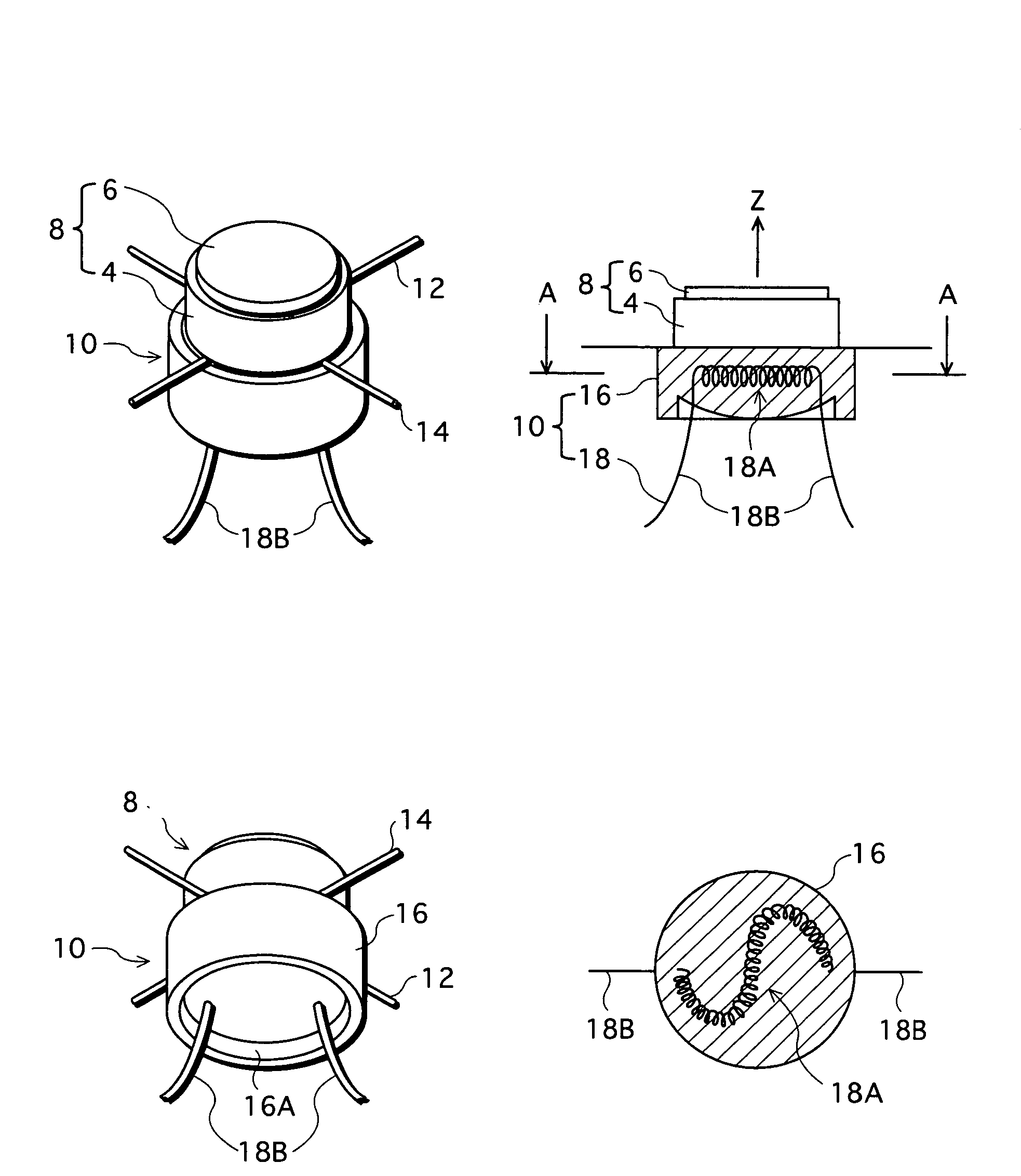
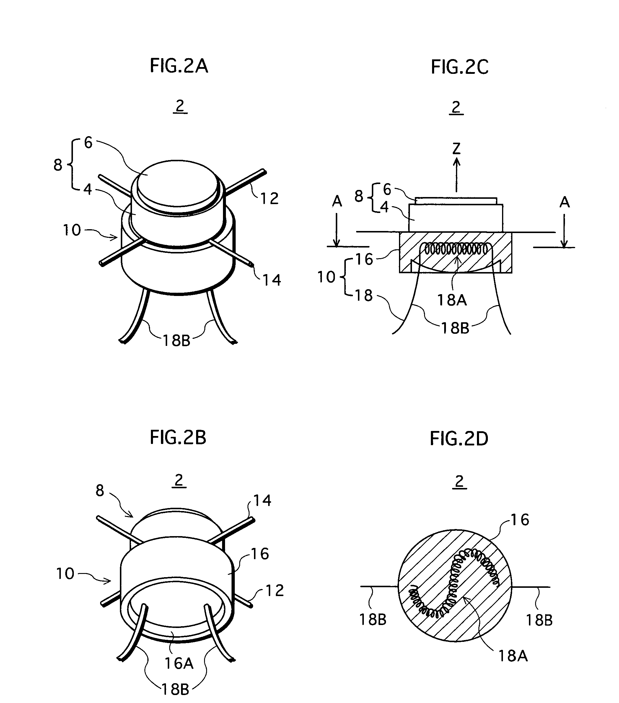
[0061]FIGS. 2A, 2B, 2C, and 2D illustrate a cathode structure 2 according to a first embodiment. FIG. 2A is a perspective view of the cathode structure 2 viewing from an angle from the top, and FIG. 2B is a perspective view of the same from an angle from the bottom. FIG. 2C is a partial cross-sectional view of a heater 10 which is to be described later, and FIG. 2D is a cross-sectional view taken at line A-A in FIG. 2C. For convenience, the cross-sectional views in FIGS. 2C and 2D only show cross-sections of a ceramic (electric insulating material) body 16 and not for a coiled part 18A.

[0062]The cathode structure 2 includes a cathode unit 8 having a cylindrical metal cup 4 and a circular columnar pellet 6 that is set in the metal cup 4, and a heater 10 that is almost circular columnar. The cathode structure 2 is structured in such a manner that the metal cup 4 and the heater 10 are connected each other, with supporting metal wires 12 and 14 crossing each other interposed between the...

second embodiment

[0124]A second embodiment is different from the first embodiment in a structure of the heater of the cathode structure. Other components, such as the electron gun, are the same as the first embodiment. Therefore, explanation is given mainly to a different part from the first embodiment.

[0125]FIGS. 13A and 13B illustrate a cathode structure 52 of the second embodiment. FIG. 13A is a side view of the cathode structure 52, and FIG. 13B is a perspective view of the cathode structure 52, viewing from an angle from the bottom.

[0126]In the cathode structure 52 according to the second embodiment, the heating wire 18 leads out from a side surface of a circular columnar ceramic body 54. The cathode structure 52 includes a large diameter part 54B between the exposed surface of the pellet 6 (electron emitting surface) and a part from which the heating wire 18 leads out of the side surface. A diameter of the ceramic body at the large diameter part 54B is larger than that at the part from which t...


PUM

PropertyMeasurementUnit
diameteraaaaaaaaaa
diameteraaaaaaaaaa
heightaaaaaaaaaa

Abstract

A cathode structure comprises a heater including a columnar ceramic body and a heating wire that is partially buried in the ceramic body, and a cathode unit disposed at a first end surface of the ceramic body. The heating wire leads out from a second end surface of the ceramic body.

Description

[0001]This application is based on application No. 2003-9749 filed in Japan, the content of which is hereby incorporated by reference.BACKGROUND OF THE INVENTION[0002](1) Field of the Invention[0003]The present invention relates to a cathode structure, an electron gun including the cathode structure, and a cathode ray tube including the electron gun.[0004](2) Description of the Related Art[0005]A cathode structure is a component of an electron gun that is included in a cathode ray tube, and it is desired that the cathode structure is made as short as possible in a direction of a tube axis in order to reduce a size of the electron gun in the direction of the tube axis and the cathode ray tube that includes the electron gun. In terms of power consumption, it is also desirable that a heater for heating an electron-emitting material may be heated up as efficiently as possible.[0006]An example of such cathode structures is disclosed in Japanese Laid-Open Patent Application No. 2001-20289...

Claims


Application Information

Patent Timeline
Patent Type & Authority Patents(United States)
IPC IPC(8): H01J1/24H01J19/10H01J19/18H01J19/48H01J1/22H01J19/16H01J29/04
CPCH01J1/22H01J29/04H01J1/24
Inventor YAMAMOTO, YOJIYAMAGISHI, MIKANAKAGAWA, SATORU
Owner PANASONIC CORP
Why Eureka
Try Eureka