
Laser radar mounting structure

a technology of mounting structure and laser radar, which is applied in the direction of instruments, vehicle components, measurement devices, etc., can solve the problems of inability to accurately detect objects, gap between beams, and inability to detect objects, so as to improve the accuracy of detecting objects around the vehicle, the effect of avoiding incident and avoiding the effect of affecting the accuracy of detecting objects

Pending Publication Date: 2022-01-06
TOYOTA JIDOSHA KK
View PDF0 Cites 0 Cited by
  • Summary
  • Abstract
  • Description
  • Claims
  • Application Information

AI Technical Summary

Benefits of technology

This patent is about a way to improve the accuracy of detecting objects around a vehicle using laser radar. The structure can help to make this easier and more effective.

Problems solved by technology

In such a laser radar, there are gaps between the beams.
Therefore, there may be a case where the object cannot be detected when the object is located between the emitted beams.
Therefore, despite the use of two laser radars, the object could not be detected accurately.

Method used


Image

  • Laser radar mounting structure
  • Laser radar mounting structure
  • Laser radar mounting structure

Examples


Embodiment Construction

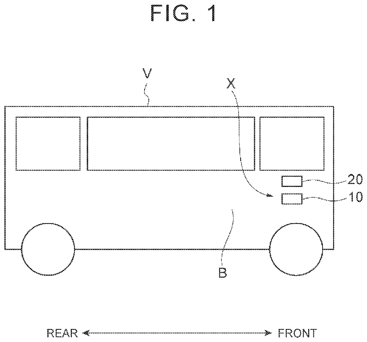
[0027]Hereinafter, an exemplary embodiment will be described with reference to the drawings. In the drawings, the same or corresponding elements will be denoted by the same reference signs, without redundant description. In the following description and the drawings, “front”, “rear”, “left”, and “right” are defined based on a vehicle V or V1.

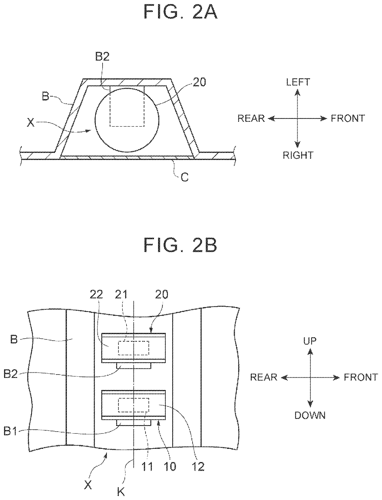
[0028]As shown in FIG. 1, a laser radar mounting structure X is a structure in which a first laser radar 10 and a second laser radar 20 are mounted to a side surface of a vehicle body of the vehicle V. The vehicle V may perform autonomous driving or provide driving support to a driver using detection results of the first laser radar 10 and the second laser radar 20. The vehicle V may be, for example, a bus on which a large number of passengers can board.

[0029]Although FIG. 1 shows a configuration in which the first laser radar 10 and the second laser radar 20 are mounted to a right side surface of the vehicle V with a laser radar mounting struct...


PUM


Abstract

A laser radar mounting structure is a structure in which a first laser radar and a second laser radar for detecting an object around a vehicle are mounted to the vehicle. A detection direction of the first laser radar and a detection direction of the second laser radar are the same as each other. The first laser radar and the second laser radar are mounted such that a first light emitting unit and a second light emitting unit are located at different height positions.

Description

CROSS-REFERENCE TO RELATED APPLICATION[0001]This application claims priority to Japanese Patent Application No. 2020-115494 filed on Jul. 3, 2020, incorporated herein by reference in its entirety.BACKGROUND1. Technical Field[0002]The present disclosure relates to a laser radar mounting structure.2. Description of Related Art[0003]For example, Japanese Unexamined Patent Application Publication No. 5-100029 (JP 5-100029 A) describes a vehicle equipped with a laser radar that detects an object. Two laser radars are mounted to the front part of the vehicle, and the two laser radars are used to detect an object in front of the vehicle.SUMMARY[0004]The laser radar described above detects an object by irradiating multiple positions in the detection region with beams. In such a laser radar, there are gaps between the beams. Therefore, there may be a case where the object cannot be detected when the object is located between the emitted beams. In the device described in JP 5-100029 A, two la...

Claims


Application Information

Patent Timeline
Patent Type & Authority Applications(United States)
IPC IPC(8): G01S7/481G01S17/931
CPCG01S7/4813G01S17/931B60R11/00B60R2011/0042G01S17/87
Inventor HOKAI, KEISUKEHAYASAKA, SHOICHIURANO, HIROMITSUYOSHIKAWA, SHUICHI
Owner TOYOTA JIDOSHA KK
Learn More