Display panel and method for fabricating same

Active Publication Date: 2022-01-06
WUHAN CHINA STAR OPTOELECTRONICS SEMICON DISPLAY TECH CO LTD
View PDF0 Cites 1 Cited by
  • Summary
  • Abstract
  • Description
  • Claims
  • Application Information

AI Technical Summary

Benefits of technology

[0004]The present disclosure provides a display panel and a method for fabricating the sam

Problems solved by technology

Furthermore, the polarizers greatly reduce light extraction efficiency of the display pane

Method used


Image

  • Display panel and method for fabricating same

Examples


Embodiment Construction

[0024]The following description of various embodiments of the present disclosure with reference to the accompanying drawings is used to illustrate specific embodiments that can be practiced. Directional terms mentioned in the present disclosure, such as “above”, “below”, “front”, “rear”, “left”, “right”, “inside”, “outside”, “side”, are merely used to indicate the direction of the accompanying drawings. Therefore, the directional terms are used for illustrating and understanding the present disclosure rather than limiting the present disclosure. In the figures, elements with similar structures are indicated by the same reference numerals.

[0025]The present disclosure provides a display panel and a method for fabricating the same to improve transmittance of the display panel and reduce thickness of the display panel.

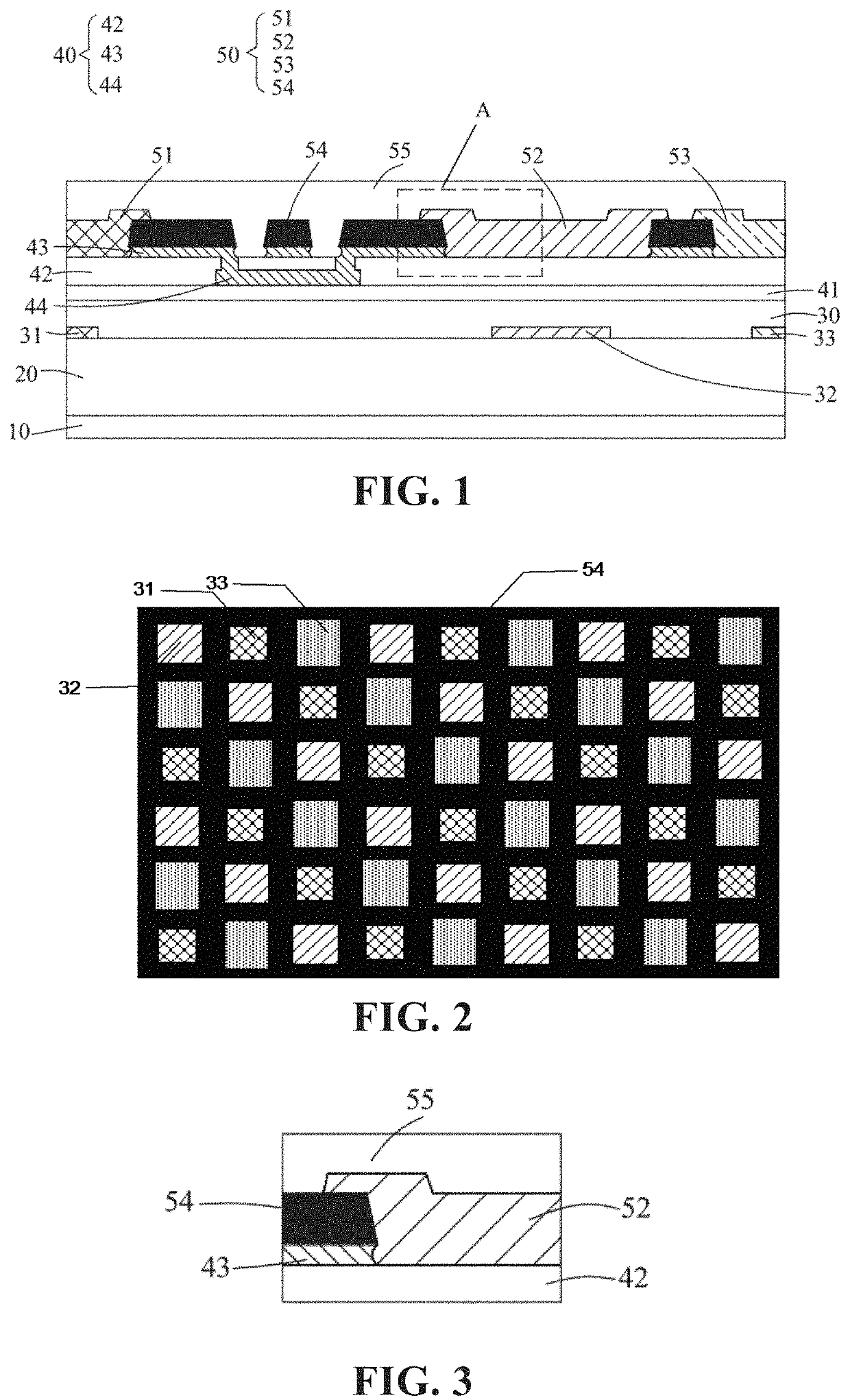
[0026]Please refer to FIG. 1 to FIG. 3. FIG. 1 is a schematic structural diagram of a display panel according to an embodiment of the present disclosure. FIG. 2 is a top v...


PUM


Abstract

The present disclosure provides a display panel and a method for fabricating the same. The display panel includes a light-emitting layer, a touch layer, a light-shielding layer, a plurality of filters, and an insulating protective layer. The light-emitting layer includes a plurality of light-emitting units. The touch layer is disposed on the light-emitting layer and provided with a plurality of grooves. The grooves are disposed corresponding to the light-emitting units. The light-shielding layer is disposed on the touch layer. The filters are disposed in the grooves of the touch layer. The insulating protective layer covers the touch layer, the light-shielding layer, and the filters.

Description

FIELD OF INVENTION[0001]The present disclosure relates to the field of electronic displays, and particularly to a display panel and a method for fabricating the same.BACKGROUND[0002]In order to reduce thickness of an electronic device with a touch function, in the prior art, a touch structure is usually integrated directly on a display panel by direct on touch (DOT) technology. Compared with an external touch structure, a DOT structure is thinner and lighter and has a higher transmittance, and can be applied to a flexible display panel.[0003]In the prior art, a DOT structure is integrated on a polarizing layer of a display panel. The polarizing layer is composed of polarizers and is configured to reduce reflectance of the display panel under strong light. Generally, thickness of each polarizer is about 100 micrometers, which is not conducive to reducing thickness of a display panel. Furthermore, the polarizers greatly reduce light extraction efficiency of the display panel, affect d...

Claims


Application Information

Patent Timeline
IPC IPC(8): H01L27/32H01L51/56
CPCH01L27/3211H01L27/323G06F3/041H01L51/56H01L27/322H01L27/3272H10K59/352H10K59/38H10K59/10H10K59/131G06F2203/04103G06F3/0412H10K59/40H10K50/865H10K59/35H10K59/126H10K71/00
Inventor LI, YUANHANG
Owner WUHAN CHINA STAR OPTOELECTRONICS SEMICON DISPLAY TECH CO LTD
Why Eureka
Try Eureka