
Communicating over a free-space optical channel using distribution matching

a distribution matching and optical channel technology, applied in the direction of electromagnetic transmission, electrical apparatus, electromagnetic transceivers, etc., can solve the problems of low cost, power consumption, computational complexity, and severe performance degradation

Active Publication Date: 2022-01-06
KING ABDULLAH UNIV OF SCI & TECH
View PDF0 Cites 1 Cited by
  • Summary
  • Abstract
  • Description
  • Claims
  • Application Information

AI Technical Summary

Benefits of technology

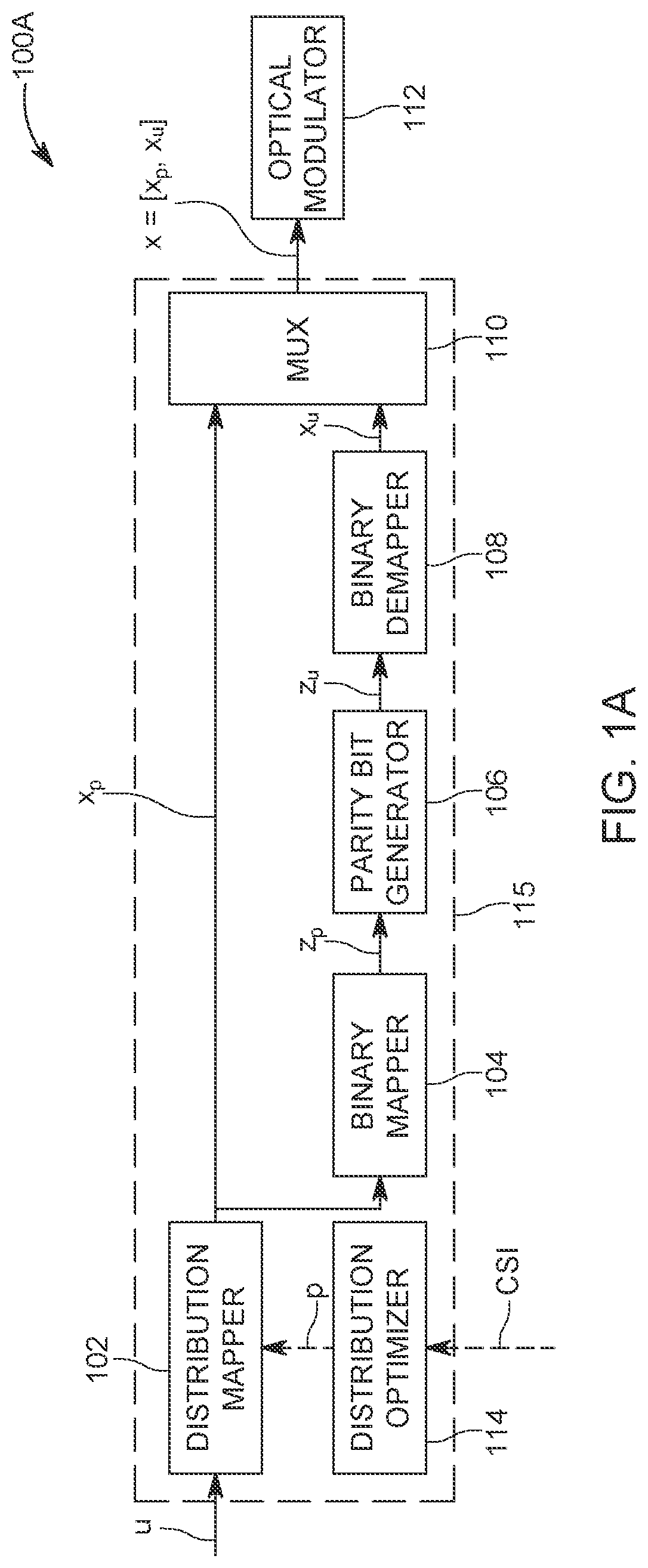
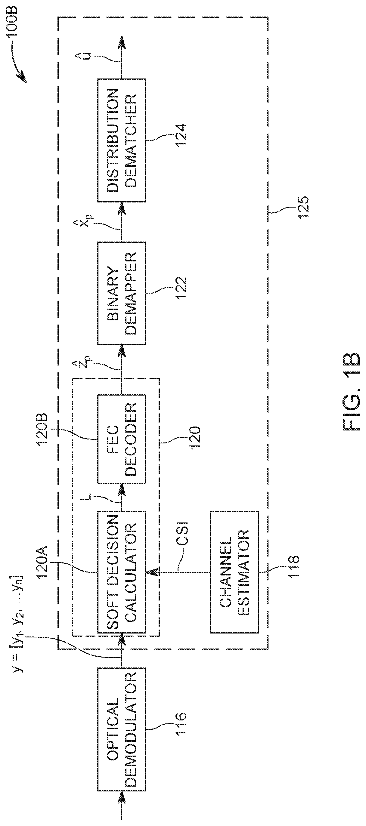
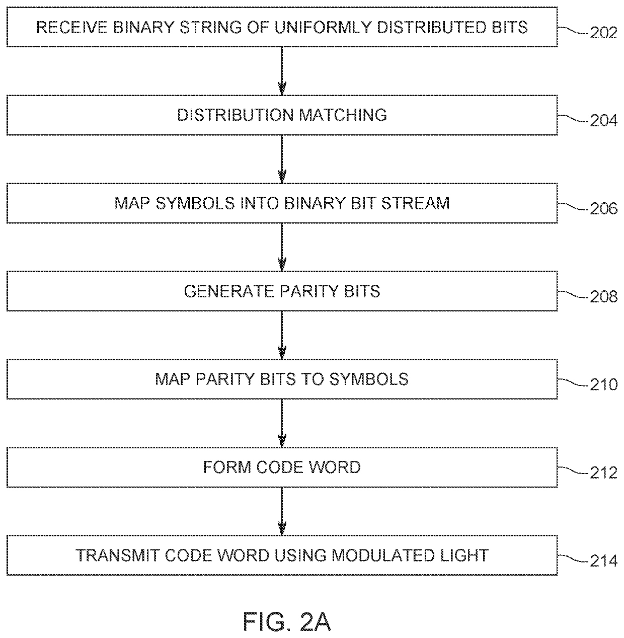
The patent describes a method for optical communication between two transceivers over a free-space medium using a binary string of bits. The method involves converting the bits into probabilistically-shaped unipolar M-pulse amplitude modulated (M-PAM) symbols, mapping the symbols into a binary bit stream, generating parity bits from the bit stream, mapping the parity bits to uniformly-distributed unipolar M-PAM parity symbols, and multiplexing the M-PAM symbols and parity symbols to form a codeword. The codeword is then transmitted over the channel to the receiver, which demodulates the optical signal and estimates the channel. The receiver decodes the signal using the estimated channel and generates a set of bits that correspond to the original binary string. The technical effect of this patent is to provide a reliable and efficient method for optical communication over a free-space medium.

Problems solved by technology

However, these frequencies are limited resource allocated by governmental authorities and these frequencies are becoming quite congested.
Free-space optical communications are subject to time-variant atmospheric turbulence, which can cause severe degradation in the performance, as the quality of the free-space optical link continuously varies with time.
Free-space optical communication systems typically employ IM / DD instead of coherent modulation techniques typically used radio frequency (RF) based systems, which is due to its low cost, power consumption, and computational complexity.
Due to the differences between radio frequency and optical communications, the signal constellation for free-space optical communications with IM / DD has the additional constraints that the input signal is subject to non-negative signaling and average optical power constraints.
The design of efficient coded modulation systems fulfilling these requirements is challenging.
Additionally, finite length forward error correction (FEC) codes are implemented in practice, which results in a coding gap.
Finally, the number of allowable modulation orders and coding rates to choose among are limited by the targeted system complexity, leading to partially-adaptive systems.
The spectral efficiency of this technique is low compared to higher-order modulations, and accordingly the transmission data rates are likewise limited.
Further, this technique is designed to consider the average electrical power constraint for the signal, whereas free-space optical communications are subject to average optical power constraints for intensity channels.
Additionally, since this technique assumes an AWGN channel, it does not capture or adapt to diverse channel conditions in free-space optical channels such as the turbulence-induced fading.
Therefore, probabilistic amplitude shaping is only suitable for bipolar input signals and cannot be directly extended to IM / DD in free-space optical channels due to the constellation symbols being constrained to be non-negative, i.e., unipolar signaling.
Further, the technique disclosed in Reference Document [1] uses multi-level coding (MLC) with multi-stage decoding (MSD), which requires the encoder to have multiple forward error correction encoders to generate the probabilistically shaped symbols with the desired distribution and the receiver to include a multi-stage decoder, which results in error propagation and long latency due to the successive decoding of bit levels.
Thus, the input distribution cannot be fully optimized to match the capacity-achieving distribution of the channel, leading to an increased shaping gap and a rate loss.

Method used


Image

  • Communicating over a free-space optical channel using distribution matching
  • Communicating over a free-space optical channel using distribution matching
  • Communicating over a free-space optical channel using distribution matching

Examples


Embodiment Construction

[0026]The following description of the exemplary embodiments refers to the accompanying drawings. The same reference numbers in different drawings identify the same or similar elements. The following detailed description does not limit the invention. Instead, the scope of the invention is defined by the appended claims. The following embodiments are discussed, for simplicity, with regard to the terminology and structure of backhaul communications over a free-space optical channel. However, it should be recognized that the disclosed embodiments are applicable for any type of free-space optical communications.

[0027]Reference throughout the specification to “one embodiment” or “an embodiment” means that a particular feature, structure, or characteristic described in connection with an embodiment is included in at least one embodiment of the subject matter disclosed. Thus, the appearance of the phrases “in one embodiment” or “in an embodiment” in various places throughout the specificat...


PUM


Abstract

A method for optical communication between first and second transceivers over a channel in a free-space medium involves receiving a binary string of uniformly distributed bits and converting them into probabilistically-shaped unipolar M-pulse amplitude modulated (M-PAM) symbols using distribution matching. The probabilistically-shaped unipolar M-PAM symbols are mapped into a binary bit stream, which are used to generate, at a forward error correction rate, parity bits. The parity bits are mapped to uniformly-distributed unipolar M-PAM parity symbols. The probabilistically-shaped unipolar M-PAM symbols and the uniformly-distributed unipolar M-PAM parity symbols are multiplexed to form a codeword that is used to modulate the intensity of a laser so as to transmit the codeword.

Description

CROSS-REFERENCE TO RELATED APPLICATIONS[0001]This application claims priority to U.S. Provisional Patent Application No. 63 / 044,044, filed on Jun. 25, 2020, entitled “ADAPTIVE CODED MODULATION FOR FREE-SPACE OPTICAL BACKHAULING,” the disclosure of which is incorporated herein by reference in its entirety.BACKGROUNDTechnical Field[0002]Embodiments of the disclosed subject matter generally relate to systems and methods for communicating over a free-space optical channel with intensity modulation / direct detection (IM / DD) using probabilistic shaping to generate probabilistically shaped unipolar M-ary pulse amplitude modulation (M-PAM) symbols, approaching the channel capacity.Discussion of the Background[0003]Efforts to increase available data rates in cellular networks are starting to focus on dense placement of small cells. Each cell requires a backhaul communication link to communicate information between the cell and the core cellular network. Backhaul communication links have conve...

Claims


Application Information

Patent Timeline
IPC IPC(8): H04B10/524H04B10/11H04B10/50H04B10/40
CPCH04B10/524H04B10/40H04B10/503H04B10/11
Inventor ELZANATY, AHMED MOHAMEDALOUINI, MOHAMED-SLIM
Owner KING ABDULLAH UNIV OF SCI & TECH
Learn More