Bendable Device

a bendable device and bendable technology, applied in the field of bendable devices, can solve problems such as large local stress, and achieve the effects of small overall modulus, large overall modulus, and large stress

Inactive Publication Date: 2022-01-13
SHENZHEN ROYOLE TECH CO LTD
View PDF0 Cites 0 Cited by
  • Summary
  • Abstract
  • Description
  • Claims
  • Application Information

AI Technical Summary

Benefits of technology

[0004]To overcome the existing problem in the related art, the present disclosure mainly aims to provide a bendable device capable of releasing stress in a bending process, thus avoiding the local stress.
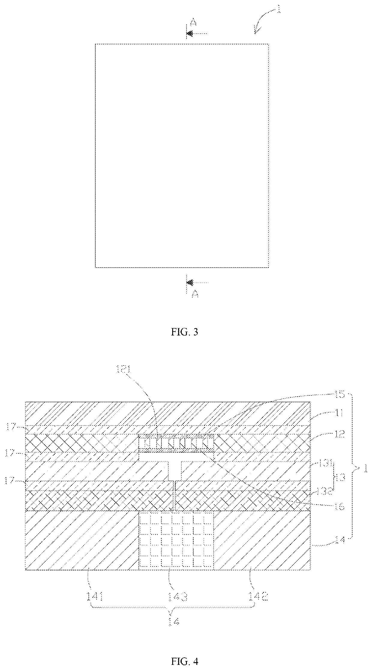
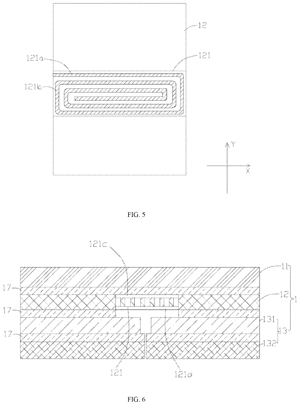
[0016]Compared with the prior art, the bendable device of the present disclosure comprises a bending layer, a supporting layer and a flexible layer arranged in a laminated manner successively, wherein the supporting layer comprises a hollow pieces which is arranged by corresponding to the bendable component, and the hollow pieces comprises at least one first branch with the vertical component, so that stacked material at a hollow portion of the hollow pieces has a small overall modulus, and stacked material of a non-hollow portion has a large overall modulus due to a large material modulus of the supporting layer. When bending the bendable device, the large stress could be released, i.e., released to the first branch, thus avoiding the large local stress of the bendable device.

Problems solved by technology

However, during bending the existing bendable electronic device, stress could not be released, causing the large local stress.

Method used


Image

  • Bendable Device
  • Bendable Device
  • Bendable Device

Examples


Embodiment Construction

[0028]To make the purpose, the technical solution and the advantages of the present disclosure more clear, the present disclosure will be further described below in detail in combination with the drawings and the embodiment. It should be understood that the specific embodiments described herein are only used for explaining the present disclosure, not used for limiting the present disclosure.

[0029]Unless otherwise specifically regulated and defined, the terms such as “first” and “second” in the illustration of the present disclosure are only used for the purpose of description, rather than being understood to indicate or imply relative importance. Unless otherwise specified, the term “a plurality of” means two or more; terms such as “connecting”, “fixation” and the like shall be understood in broad sense, and for example, “connecting” may refer to fixed connection or detachable connection or integral connection, or electrical connection, and may refer to direct connection or indirect...


PUM

PropertyMeasurementUnit
flexibleaaaaaaaaaa
stressaaaaaaaaaa
modulusaaaaaaaaaa

Abstract

The present disclosure discloses a bendable device. The bendable device comprises a screen layer, a supporting layer and a bending layer, wherein the bending layer comprises a first main body, a second main body and a bendable component. The first main body is connected with the second main body through the bendable component, the bending layer, the supporting layer and a flexible layer are arranged in a laminated manner successively. In the present disclosure, the supporting layer comprises the hollow pieces, the hollow pieces comprising the at least one first branch with the vertical component, so that stacked material at a hollow portion of the hollow pieces has a small overall modulus, and stacked material of a non-hollow portion has a large overall modulus due to a large material modulus of the supporting layer. When bending the bendable device, the large stress could be released.

Description

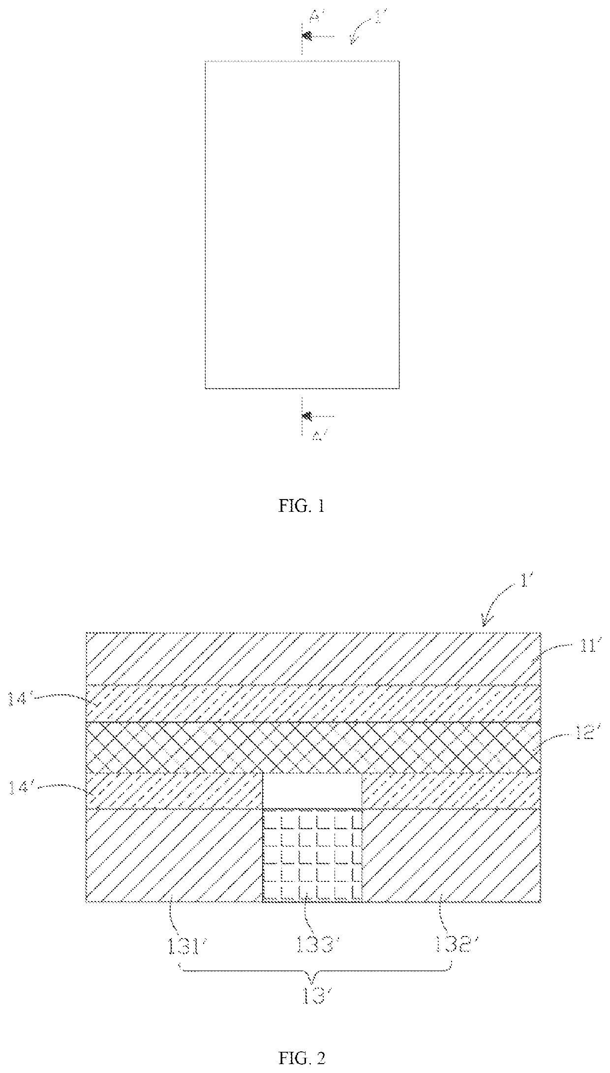
TECHNICAL FIELD[0001]The present disclosure relates to the technical field of electronic industry, and particularly to a bendable device.BACKGROUND ART[0002]Referring to FIGS. 1 and 2, an existing bendable electronic device 1′ generally comprises a flexible screen 11′, a supporting layer 12′ and a bending layer 13′ which are arranged in a laminated manner successively. The supporting layer 12′ is a whole block, connected to the flexible screen 11′ and the bending layer 13′ through glue layers 14′, and plays a role in supporting and protecting the flexible screen 11′. The bending layer 13′ comprises a first main body 131′, a second main body 132′ and a bendable component 133′, and the first main body 131′ is connected with the second main body 132′ through the bending component 133′.[0003]However, during bending the existing bendable electronic device, stress could not be released, causing the large local stress.SUMMARY OF THE INVENTION[0004]To overcome the existing problem in the re...

Claims


Application Information

Patent Timeline
Patent Type & Authority Applications(United States)
IPC IPC(8): B32B27/08B32B7/12B32B3/20B32B3/30
CPCB32B27/08B32B7/12B32B2307/546B32B3/30B32B2307/51B32B3/20H04M1/0268B32B27/281B32B15/18B32B2307/518B32B2457/20B32B27/40B32B27/36B32B2307/54B32B2457/208B32B15/20B32B15/14B32B3/26B32B5/028B32B15/09B32B15/043G06F3/03547G06F3/041G06F2203/04102G06F2203/04103G06F2203/04107G09G3/035G09G2380/02G09G2300/043
Inventor XUE, XIAOFEICHEN, SONGYA
Owner SHENZHEN ROYOLE TECH CO LTD
Why Eureka
Try Eureka