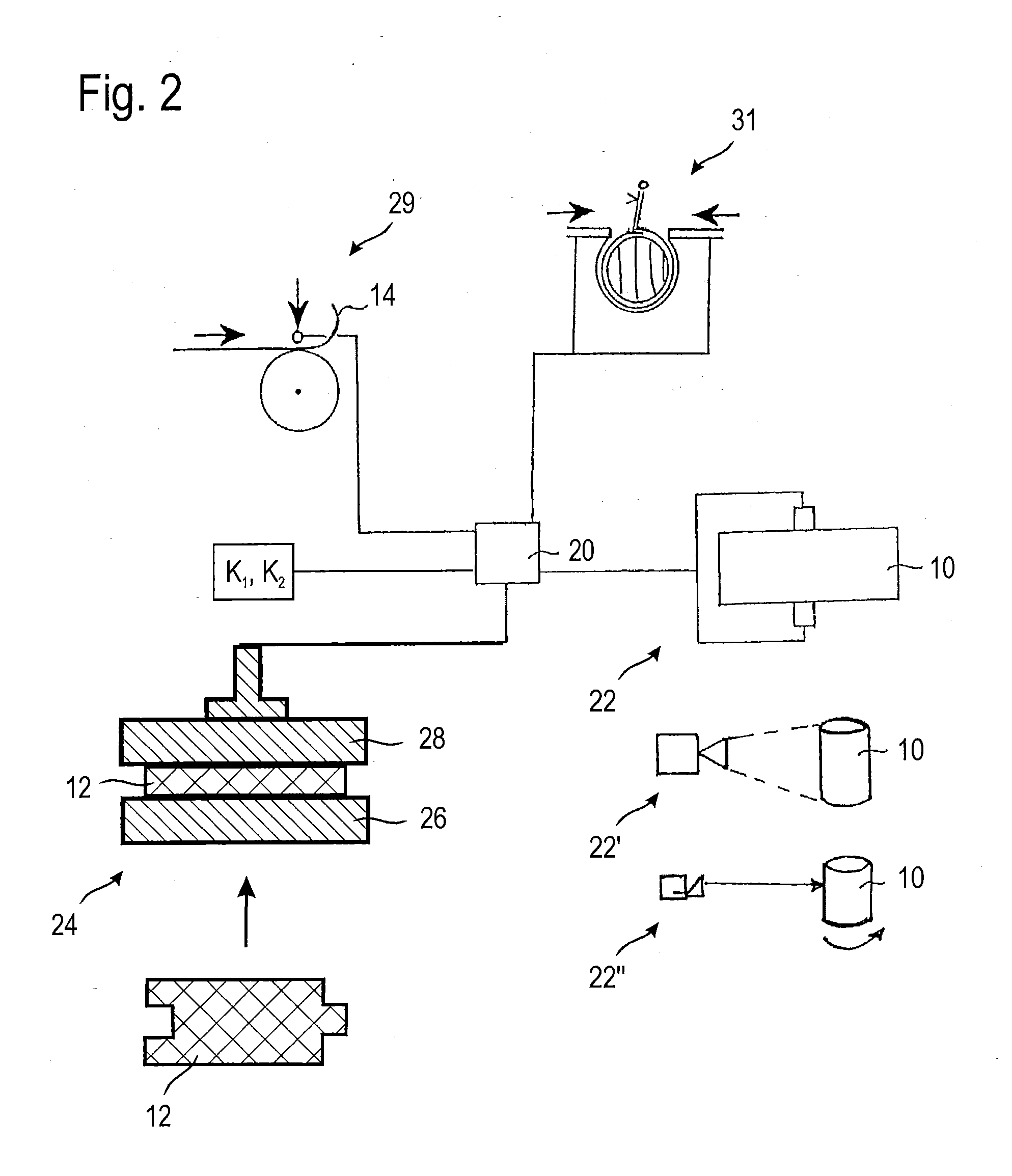
[0013]In contrast to the aforementioned prior art, the compensating element, in general a bearing mat, is subjected to a full-surface load, in order to plot a deformation-
pressure curve. Due to this full-
surface loading, the above-mentioned problems with regard to the identification of representative partial areas are solved automatically. In addition, the load-pressure curves of compensating elements subjected to a full-surface load are relatively robust with respect to minor changes in the marginal conditions, i.e. they are much less dependent on exact, laboratory-
scale test conditions. Consequently, excellent results can also be achieved with acceptable effort in a
mass production.
[0017]In this method variant, the setpoint deformation might however also be extrapolated in step b) from the deformation when applying pressure up to the predetermined test limit and might additionally be adapted by a correction value, wherein the correction value considers influences of the
assembly in step e) on the deformation behavior of the compensating element. Between the deformation behavior when plotting the compression curve and the future built-in condition a
systematic deviation exists, which is caused by the respective
assembly method. The correction value eliminates or reduces this
systematic error and generally is empirically determined for a concrete
assembly method.
[0018]In another method variant, the setpoint pressure and the predetermined test limit lie in a damaging range of the compensating element, wherein in step b) the setpoint deformation is interpolated or extrapolated from the deformation when applying pressure up to the predetermined test limit and additionally is adapted by a correction value, wherein the correction value considers a damage of the compensating element during the application of pressure up to the predetermined test limit. Due to this increase of the predetermined test limit up into the damaging range of the compensating element, the inaccuracy or the error during extrapolation of the compression curve is distinctly reduced. In this case, however, the setpoint deformation obtained also is adapted by a correction value, which considers the “damage” (e.g. due to
fiber breakage or irreversible alignment of the fibers) during the application of pressure up to the predetermined test limit. In general, this correction value is determined empirically for a particular group of compensating elements (same geometry, same material, same structure), so that their compression curve during the future assembly in the outer housing can be predicted very precisely.
[0019]In this method variant, the predetermined test limit can even lie above the specified setpoint pressure. The setpoint deformation of the compensating element in step b) then can be determined by interpolation, which as compared to extrapolation provides for a more precise determination of the setpoint deformation to achieve the specified setpoint pressure.
[0020]In this method variant, the setpoint deformation preferably is adapted by a further correction value, which additionally considers influences of the assembly in step e) on the deformation behavior of the compensating element. As already mentioned above, a
systematic error in the determination of the deformation behavior in the outer housing, which is dependent on the assembly method, thereby is eliminated or at least reduced.
[0022]To further optimize the future clamping of the insert in the outer housing, further parameters can be considered during or after the interpolation or extrapolation. Reference should be made here in particular to the rebound of the outer housing after the closing operation, which occurs, e.g. in wrapped housings, or the expansion of the housing (in the case of a prefabricated cylindrical outer housing into which the insert is pushed), which occurs after the assembly. Furthermore, the change in shape of the outer housing, which occurs in the case of changes in temperature (inevitable in operation of the exhaust gas cleaning device), advantageously should be considered; especially housings with a non-round cross-section tend to “become round”. If this tendency is already taken into account when determining the individually tailor-made outer housing for the respective insert, in that for example an oval housing is made slightly more oblong,
local pressure peaks in the regions with a smaller
radius can be avoided. In this way, a smaller substrate load is obtained, which results in less
scrap and a better durability.