Active Lift Control Device and Method

a technology of active lifts and control devices, which is applied in the direction of machines/engines, machine/engines, air-flow influencers, etc., can solve the problems of structural fatigue or catastrophic load, unsteady force of lifting surfaces, and high construction costs, so as to increase the lift, increase the pressure, and increase the lift

Active Publication Date: 2022-01-13
ARCTURA INC
View PDF0 Cites 3 Cited by
  • Summary
  • Abstract
  • Description
  • Claims
  • Application Information

AI Technical Summary

Benefits of technology

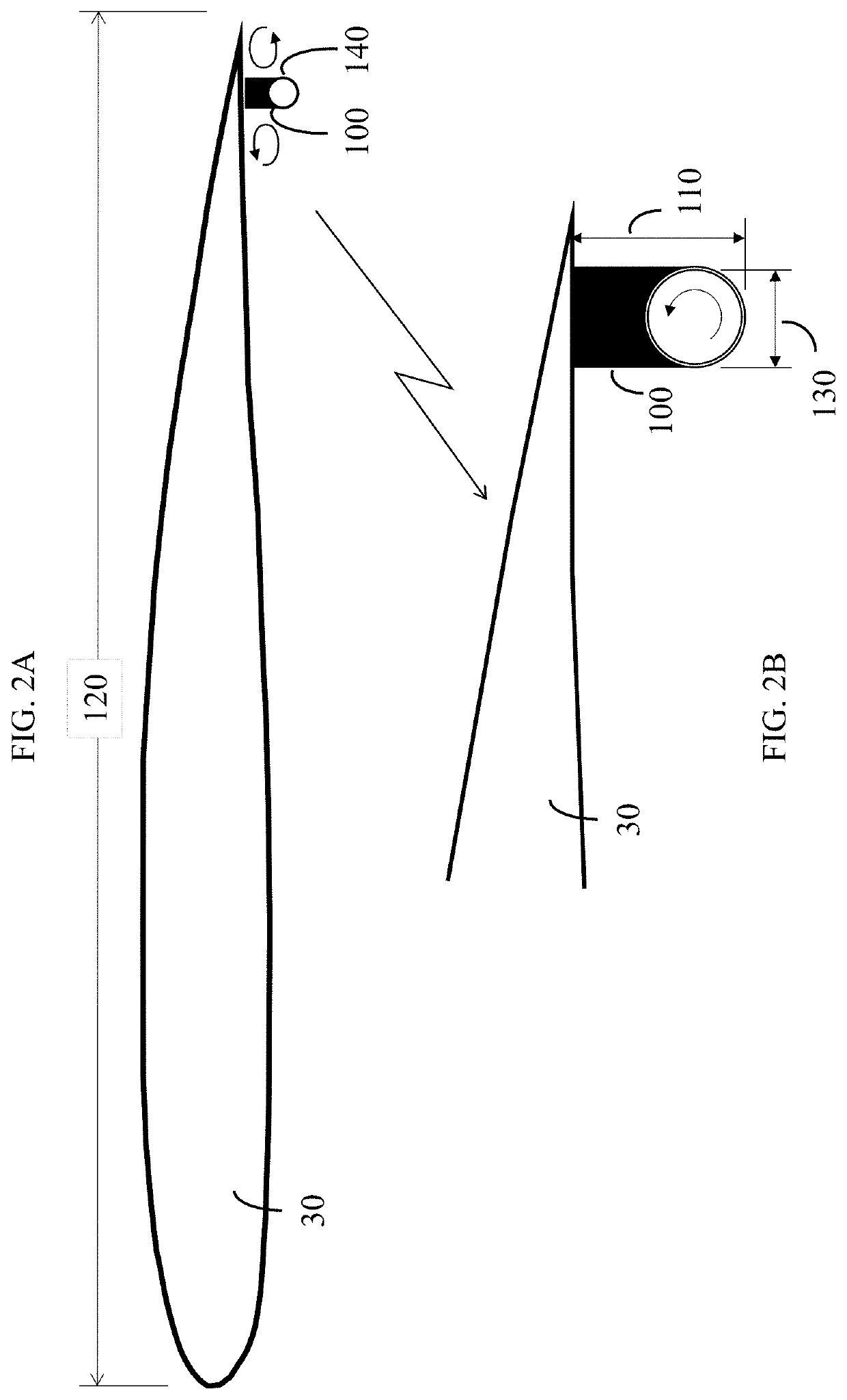
[0006]A Gurney flap is a passive device used to increase the lift generated by the flow over a lifting surface, such as a wing or wind turbine blade. A conventional Gurney flap consists of a simple rigid fence-like protuberance near the trailing edge of an airfoil. The device typically extends at right angles to the pressure side of the airfoil, and projects a distance equal to 1-3% of the wing's chord length into the flow. By producing a separated flow region just upstream and just downstream of the protuberance, the Gurney flap increases the pressure on the pressure side while keeping the boundary layer attached to suction side. This results in a significant increase in the lift in comparison to the airfoil without the Gurney flap.
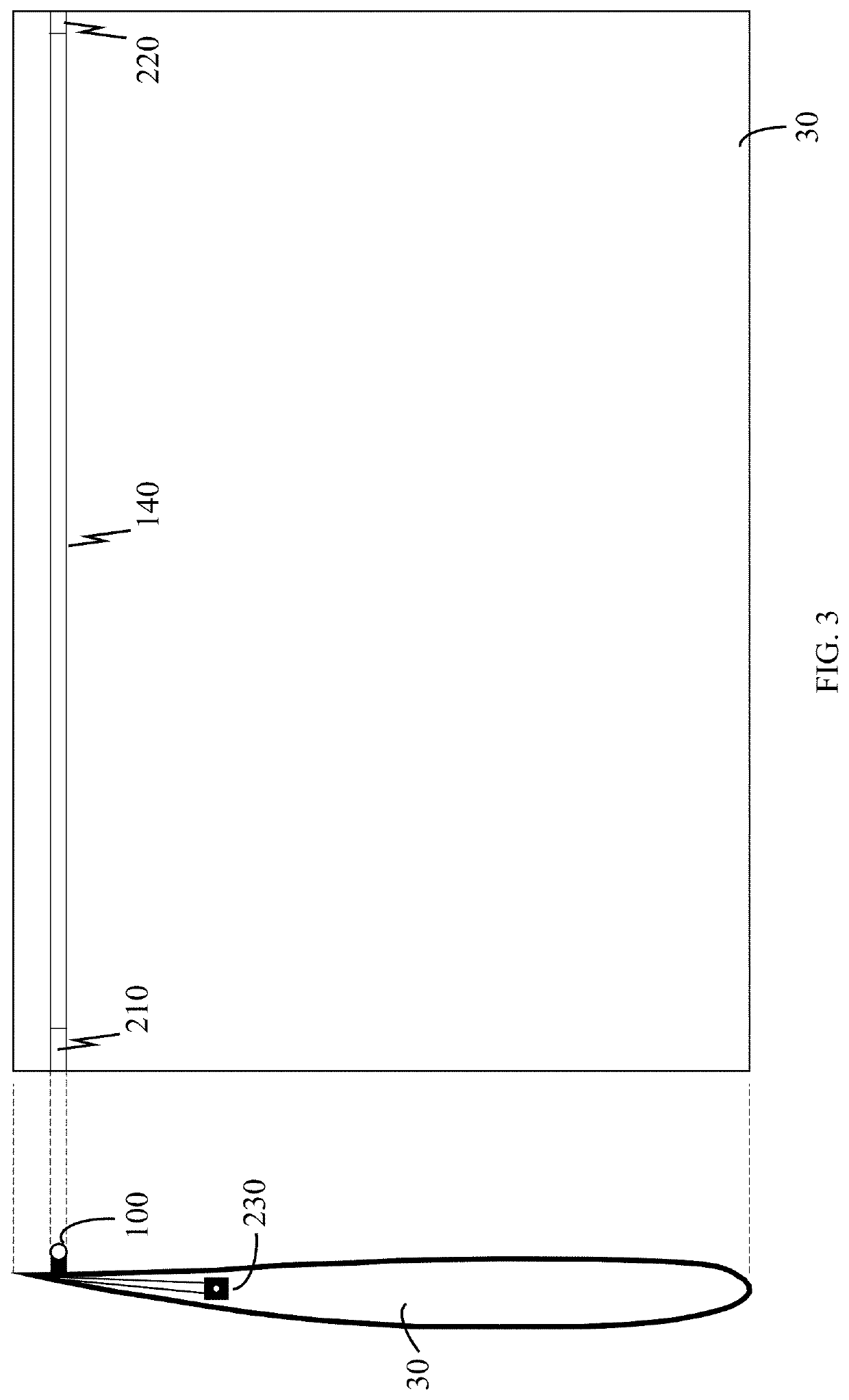
[0007]Although embodiments of the present invention bear some resemblance to the Gurney flap, unlike the Gurney flap, embodiments of the present invention provide a lift device that can be actively controlled, so that either a baseline (or minimum) lift or a maximum lift, or an intermediate lift between those values, can be obtained on demand. For example, embodiments of the present invention can be used to reduce the unsteady forces experienced by wings and wind turbine blades by modifying the lift in response to wind gusts, turbulence, and the like. Such embodiments can be controlled by a computer algorithm that is designed to minimize the undesirable effects of the unsteady forces.

Problems solved by technology

Often, lifting surfaces experience unsteady forces caused by turbulence, gusts, wind shear, unsteady currents, upstream obstacles, and the like.
Those unsteady forces lead to structural fatigue or catastrophic loads, and must be accounted for in system design.
For example, to counter the anticipated occasional unsteady forces due to wind gusts, wind turbine components must be built strong and heavy, which makes them costly to build.
Similarly, the cost and weight of materials used in the construction of airplane wings and fuselages is impacted by expected fatigue loads experienced by the wings and control surfaces.
Unfortunately, all of the active control techniques listed above are complex, and complexity leads to reliability problems, high capital cost, high energy cost, and safety issues.

Method used


Image

  • Active Lift Control Device and Method
  • Active Lift Control Device and Method
  • Active Lift Control Device and Method

Examples


second embodiment

[0057]FIG. 4A is a two-dimensional cross-sectional view of a lifting surface with the controllable lift device of the present invention. FIG. 4B provides detail in the vicinity of the protuberance 100 of FIG. 4A.

third embodiment

[0058]FIG. 5A is a two-dimensional cross-sectional view of a lifting surface with the controllable lift device of the present invention. FIG. 5B provides detail in the vicinity of the protuberance 100 of FIG. 5A.

[0059]FIG. 6A is a two-dimensional cross-sectional view of a lifting surface with the combination of the controllable lift device and a plasma actuator in accordance with an embodiment of the present invention. FIG. 6B provides detail in the vicinity of dielectric barrier discharge plasma actuators 310 of FIG. 6A.

[0060]FIG. 7 is a two-dimensional cross-sectional view of a lifting surface with the combination of the controllable lift device and a backward facing step in accordance with an embodiment of the present invention.

[0061]FIGS. 8A and 8B are a plan view and an edge view of a planar lifting surface with a semi-active embodiment of the controllable lift device in accordance with an embodiment of the present invention. FIG. 8C provides a further edge view when the liftin...

fourth embodiment

[0062]FIGS. 9A, 9B, and 9C are two-dimensional cross-sectional views of a lifting surface with the controllable lift device of the present invention.


PUM


Abstract

A lift control device actively controls the lift force on a lifting surface. The device has a protuberance near a trailing edge of its lifting surface, which causes flow to separate from the lifting surface, generating regions of low pressure and high pressure which combine to increase the lift force on the lifting surface. The device further includes a means to keep the flow attached around the protuberance or to modify the position of the protuberance in response to a command from a central controller, so as to provide an active control of the lift between a maximum value and a minimum value.

Description

RELATED APPLICATION[0001]The present application is a divisional application of U.S. patent application Ser. No. 16 / 403,010, filed May 3, 2019 (“the parent application”), which claims the benefit of U.S. provisional application Ser. No. 62 / 666,472, filed May 3, 2018. Because the present application includes disclosure going beyond that of the parent application, the present application is also a continuation in part of the parent application. Each of the foregoing applications is hereby incorporated herein by reference in its entirety.TECHNICAL FIELD[0002]The present invention relates to devices for use in active control of the lift force generated by wings, airfoils, hydrofoils, rotating turbine blades, helicopter blades, propellers, and similar lifting bodies operating in an air or water stream.BACKGROUND ART[0003]Often, lifting surfaces experience unsteady forces caused by turbulence, gusts, wind shear, unsteady currents, upstream obstacles, and the like. Those unsteady forces le...

Claims


Application Information

Patent Timeline
Patent Type & Authority Applications(United States)
IPC IPC(8): B64C23/02F15D1/00F03D7/02B64C21/10B64C23/08
CPCB64C23/02F15D1/007F03D7/022B64C21/10B64C2003/148F03D7/0232F15D1/002F03D7/0236B64C23/08F15D1/0065F15D1/12Y02E10/72B63B1/24F05B2240/304F05B2240/3052B64C3/28Y02T50/10F05B2240/3062F05B2240/305B64C2230/28
Inventor FINE, NEAL E.COONEY, JR., JOHN A.
Owner ARCTURA INC
Why Eureka
Try Eureka