
Adaptable spoiler for a wind turbine rotor blade

a technology of wind turbine rotor blades and adaptable spoilers, which is applied in the direction of wind turbines, wind motor control, motors, etc., can solve the problems of partial damage or at least the reduction of the lifetime of the spoiler, the inability to provide in all circumstances sufficient or reasonable performance of the conventional spoiler, and the inability to adapt to the needs of the wind turbin

Pending Publication Date: 2022-01-13
SIEMENS GAMESA RENEWABLE ENERGY AS
View PDF6 Cites 2 Cited by
  • Summary
  • Abstract
  • Description
  • Claims
  • Application Information

AI Technical Summary

Benefits of technology

The present invention introduces a reinforcement element made of a creep-resistant material, such as fibre reinforced plastic, that improves the rigidity and performance of a spoiler by ensuring its intended shape and maintaining constant stiffness throughout its lifetime. This allows for better control and efficiency of the vehicle's performance.

Problems solved by technology

It has however been observed that conventional spoilers do not provide in all circumstances a sufficient or reasonable performance, in order to actively change the state for example of a downstream installed flow regulating device, such as a vortex generator.
Furthermore, it has been observed that a conventional spoiler does not withstand in all situations the load it is subjected to, leading to partial damage or at least reduction of the lifetime of the spoiler.
This may be a desired effect in the inboard sections of an airfoil during normal production, but might be an unwanted or undesired effect in other situations due to the excess levels of loads.
Further, the flow around the airfoil sections may be stalled or separated from the blade surface i.e. inducing flow separation or stall) in particular situations or particular states of the spoiler.
When the flow-regulating device is operating undisturbed, the flow on the surface of the aerodynamic profile (of the rotor blade) remains attached and may lead to higher lift coefficient.
When the flow-regulating device has been counteracted in the active state of the spoiler, the flow may tend to separate from the surface of the aerodynamic profile (of the rotor blade) and may lead to both a lower lift coefficient and a higher drag coefficient.
However, the plastic piece alone may not be strong enough to withstand the load of impacting wind during wind turbine operation and the activation cycles to which it is subjected throughout the lifetime of the turbine.
The front end of the spoiler may have the highest structural risks, due to the extreme bending, and it may be the purpose of the stiffening element to be able to cope with the stress and strain due to that bending (of the front end of the spoiler or airfoil shaped surface).

Method used


Image

  • Adaptable spoiler for a wind turbine rotor blade
  • Adaptable spoiler for a wind turbine rotor blade
  • Adaptable spoiler for a wind turbine rotor blade

Examples


Embodiment Construction

[0055]Elements similar in structure and / or function are labelled with reference signs differing only in the first digit.

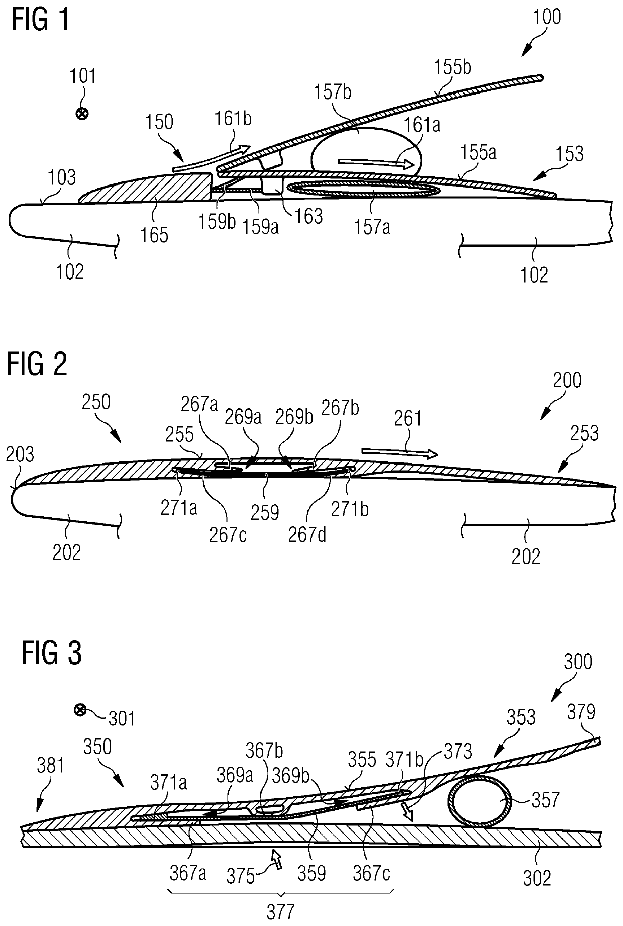
[0056]The rotor blade 100 schematically (and partially) illustrated in FIG. 1 in a side sectional view looking along the longitudinal axis 101 of the rotor blade 100 (corresponding to the longitudinal direction of the spoiler 150) comprises a blade airfoil surface 103, in particular on a suction surface which is exposed to air flow during operation of the rotor blade 100. The rotor blade 100 further comprises an adaptable spoiler 150 which is installed at the blade airfoil surface 103, in particular in a front portion of a suction surface of the rotor blade 100. The adaptable spoiler may e.g., arranged in locations between 25% and 60%, or between 30% and 45% of the front portion of the blade. The rotor blade 100 comprises a main body 102 having the airfoil shaped surface 103.

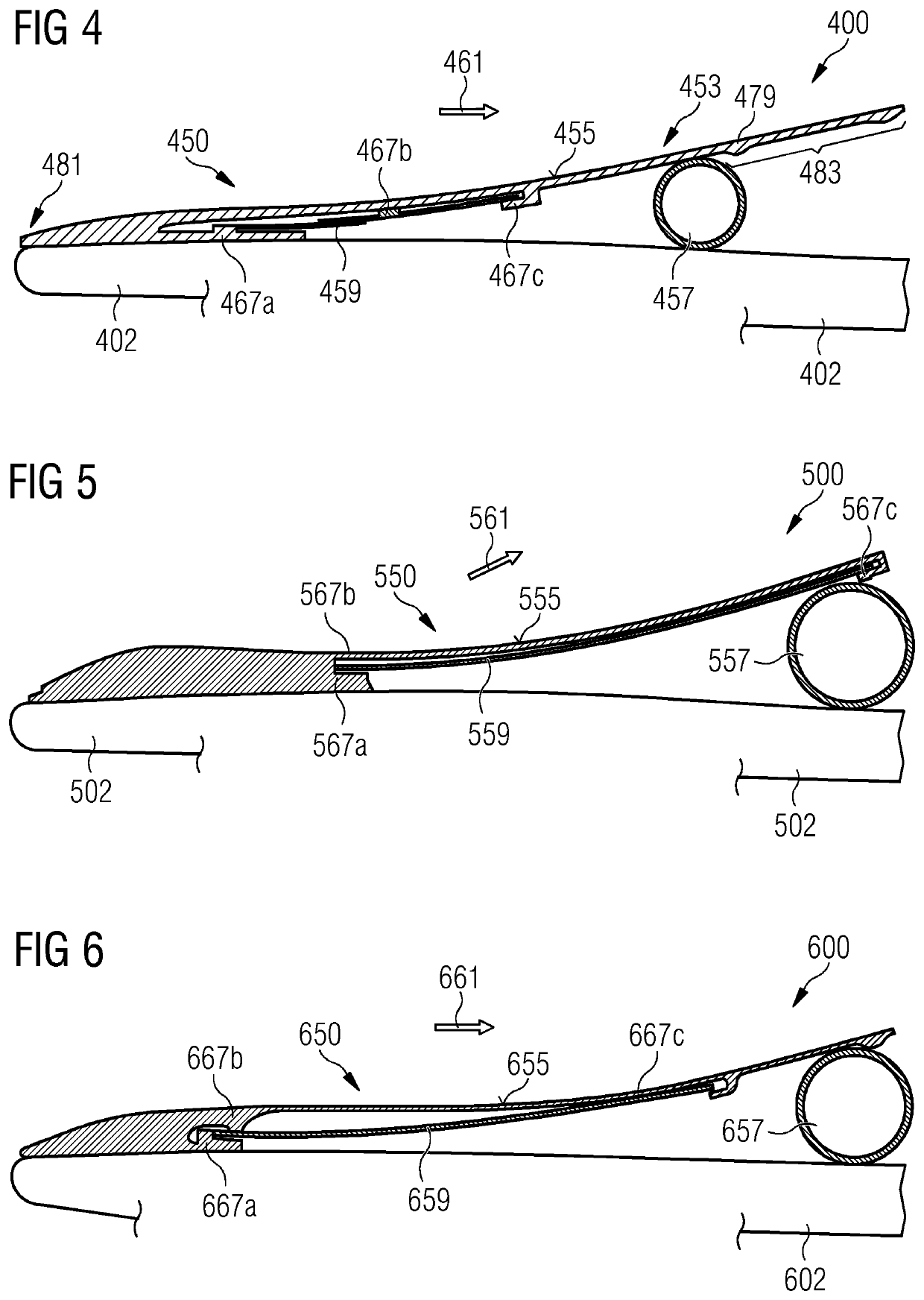
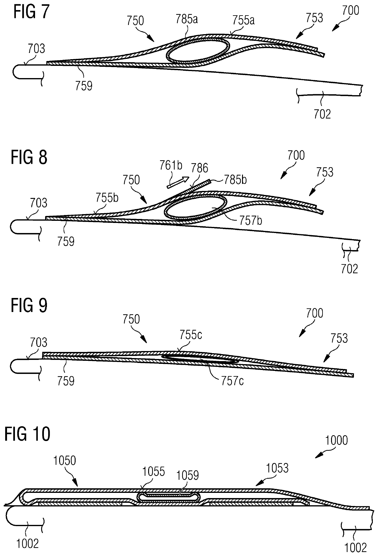
[0057]In FIGS. 1 to 10, only a front portion of the respective rotor blade is illustrated, ...


PUM

PropertyMeasurementUnit
Thicknessaaaaaaaaaa
Forceaaaaaaaaaa
Shapeaaaaaaaaaa

Abstract

Provided is a spoiler, in particular adaptable spoiler, for a wind turbine blade including: a main body including an airfoil shaped surface to be exposed to air flow; at least one stiffening element distinct from the main body and supporting the airfoil surface, wherein the stiffening element is in particular configured to enforce the shape of the airfoil surface during loading by wind during operation of the wind turbine.

Description

CROSS-REFERENCE TO RELATED APPLICATIONS[0001]This application claims priority to PCT Application No. PCT / EP2019 / 084054, having a filing date of Dec. 06, 2019, which is based on EP Application No. 18212367.9, having a filing date of Dec. 13, 2018, the entire contents both of which are hereby incorporated by reference.FIELD OF TECHNOLOGY[0002]The following relates to a spoiler, in particular an adaptable spoiler, for a wind turbine blade of a wind turbine and further relates to a rotor blade of a wind turbine comprising the spoiler.BACKGROUND[0003]A wind turbine rotor blade may have installed a flow regulating device on its surface. An example of such a flow regulating device is a vortex generator (VG). The rotor blade may further comprise a spoiler installed at the rotor blade surface. The spoiler may act in concert with the vortex generator and may influence the effect of the vortex generator depending on the state of the spoiler. The state of the spoiler may relate to a protrusion ...

Claims


Application Information

Patent Timeline
IPC IPC(8): F03D7/02F03D1/06
CPCF03D7/0232F03D1/0641F05B2280/6013F05B2240/3052F03D1/0658F03D7/0296Y02E10/72F03D1/0675
Inventor ENEVOLDSEN, PEDER BAYFIEDEL, MORITZGIRSCHIG, FLORIANGONZALEZ, ALEJANDRO GOMEZKRISTENSEN, KRISTER JUSTKRISTENSEN, MIKKEL AGGERSBJERGMICHELSEN, ANDERSNEUSCHÄFER LARSEN, HENRIK
Owner SIEMENS GAMESA RENEWABLE ENERGY AS
Learn More