Lock

a technology of locking system and lock, which is applied in the field of lock system, can solve the problems of thief unable to successfully remove the anti-theft mechanism, the thief could still cut the rope, and the bike could not be used to ride away, so as to avoid the problem of battery damage and avoid the damage of components due to forcible riding in the prior ar

Active Publication Date: 2022-01-20
TEAM YOUNG TECH CO LTD
View PDF11 Cites 1 Cited by
  • Summary
  • Abstract
  • Description
  • Claims
  • Application Information

AI Technical Summary

Benefits of technology

[0007]In view of the shortcomings of the above-mentioned existing rope lock and electronic lock, one of the objectives of the invention is to provide a lock that uses an upper-rotation shaft to connect a handlebar via a faucet, and uses a lower-rotation shaft to connect a front wheel via a front fork tube, which is simple and may be used without destructive modification of a bike. In addition, the lock of the invention adopts a design of separating a rope head and a slider, so that when the rope head is forcibly pulled out in a locking state, the slider is still remained in an original position, and the handlebar and the front wheel are maintained in a non-linked state, and the bike cannot be ridden. In addition, since a design of releasing movement linkage is adopted, damage of components due to forcible riding in the prior art is avoided. Moreover, in an embodiment of the invention, the lock does not consume power during a locking process, and the power used during an unlocking process is directly provided by an external unlocking device, i.e., a battery may be omitted in the lock to avoid the problem of battery damage.

Problems solved by technology

However, a thief could still cut the rope with a portable, small hydraulic shear, and ride the bike away.
Based on such design, even if the thief cuts the steel rope, since a head portion of the steel rope is still in the lock body, a lock pin still remains in the central shaft to prevent the crank from rotating, so that an anti-theft mechanism cannot be successfully removed by only cutting the steel rope.
First, the lock requires destructive modification of the bike before it may be installed and used; second, when the thief pulls the rope head out of the lock body by force, the return spring may automatically push the lock pin out of the central shaft, and the locking state is automatically released; third, when the thief cuts the steel rope, and rides the bike by force while the crank is locked, it may cause deformation and damage of the crank.
However, when the bike is parked or ridden in a bad environment, the battery in the electronic lock may be damaged by moisture, and the leaked battery liquid may cause corrosion or rust of the bike body.
Also, when the electronic lock has no power, the battery must be replaced, which is very inconvenient for the user.

Method used


Image

  • Lock
  • Lock
  • Lock

Examples


Embodiment Construction

[0030]In the following detailed description of the preferred embodiments, reference is made to the accompanying drawings which form a part hereof, and in which are shown by way of illustration specific embodiments in which the invention may be practiced. In this regard, directional terminology, such as “upper,”“lower,”“left,”“right,”“front,”“back,”“top”“bottom,”“side,” etc., is used with reference to the orientation of the Figure(s) being described and are not intended to be limiting of the invention.

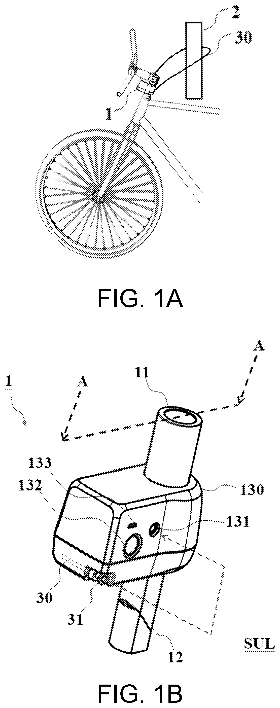
[0031]Referring to FIG. 1A and FIG. 1B, FIG. 1A and FIG. 1B are respectively a schematic diagram of a use situation of a lock applied to a bike and an appearance schematic diagram of the lock according to a first embodiment of the invention. From an appearance of a lock 1, it is known that the lock 1 has a lock body wrapped by a housing 130, and a first connecting member 11 and a second connecting member 12 respectively penetrating through upper and lower sides of the housing 130. The h...


PUM


Abstract

A lock for locking a bike is provided. To lock the bike, a user inserts a rope head into a lock through a lock hole. The rope head drives a slider in the lock, and the slider drives a pin, causing an upper-rotation shaft of the lock become not linked to move with a lower-rotation shaft of the lock. Since the upper-rotation shaft and the lower-rotation shaft of the lock are respectively connected to a handlebar and a front wheel of the bike, the user is unable to control the front wheel through the handlebar. The rope head may also be connected to a rope, and when locking the lock, the user pulls the rope out from the lock, wraps the rope around a fixed object, and then inserts the rope head into the lock through the lock hole.

Description

CROSS-REFERENCE TO RELATED APPLICATION[0001]This application claims the priority benefit of Taiwan application serial no. 109124129, filed on Jul. 16, 2020. The entirety of the above-mentioned patent application is hereby incorporated by reference herein and made a part of this specification.BACKGROUNDTechnical Field[0002]The invention relates to a lock system and an installation method thereof, and particularly relates to a lock with a plurality of protection mechanisms.Description of Related Art[0003]Rope lock is one of the existing, conventional bike locks. The principle of the rope lock is to use a rope to connect and fix a bike with an external fixed object to prevent theft. However, a thief could still cut the rope with a portable, small hydraulic shear, and ride the bike away.[0004]There is a lock that remains locked even after the rope is cut for resolving the above problem. Such lock includes three main components: a lock body, a rope, and a rope head. One end of the rope i...

Claims


Application Information

Patent Timeline
Patent Type & Authority Applications(United States)
IPC IPC(8): B62H5/00E05B71/00E05B47/00E05B73/00
CPCB62H5/003E05B73/0011E05B47/0009E05B71/00B62H5/02
Inventor LIU, CHIH-HUNG
Owner TEAM YOUNG TECH CO LTD
Why Eureka
Try Eureka