Cryogenic fluid storage tank

Active Publication Date: 2022-01-27
LAIR LIQUIDE SA POUR LETUDE & LEXPLOITATION DES PROCEDES GEORGES CLAUDE
View PDF0 Cites 2 Cited by
  • Summary
  • Abstract
  • Description
  • Claims
  • Application Information

AI Technical Summary

Benefits of technology

The present invention aims to overcome the disadvantages of prior art by integrating multiple valves into a tank, allowing for better control and management of fluid flows. The invention also includes sensors to measure pressure and a module that automatically controls the distribution of fluid based on the measured pressure. The invention allows for improved efficiency and accuracy in tank filling and provides a more reliable and automated method for controlling the pressure in the tank.

Problems solved by technology

Maintaining a constant pressure inside such tanks is difficult or unsatisfactory.
The known systems require complex adjustments.
Furthermore, the adjustments of these different devices (two or three devices) can prove to be inconsistent / conflicting.
Moreover, a complex system is often required either for implementing pressure regulation in the lower part of the tank (in the liquid part) or for safely filling the tank.

Method used


Image

  • Cryogenic fluid storage tank
  • Cryogenic fluid storage tank
  • Cryogenic fluid storage tank

Examples


Embodiment Construction

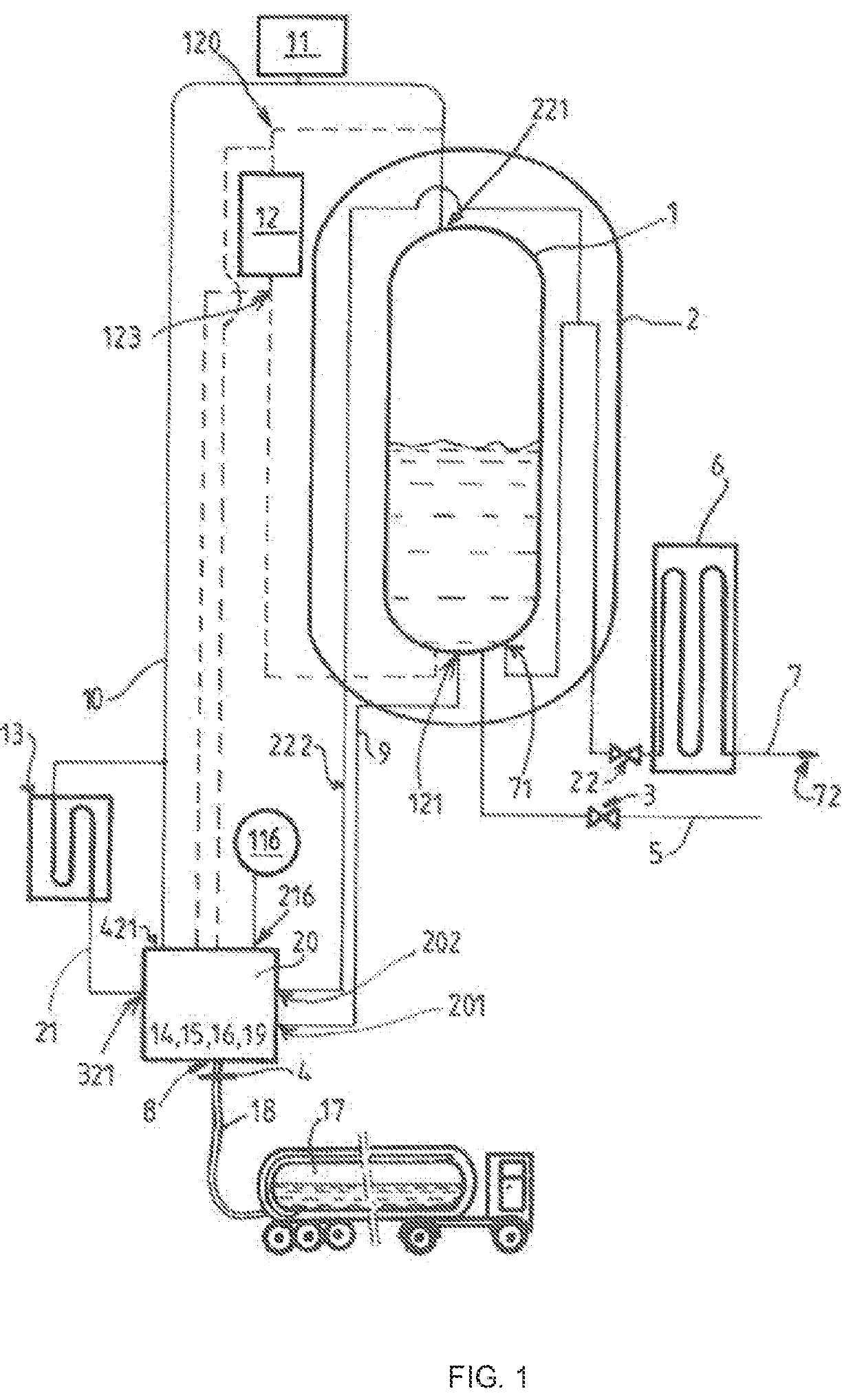
[0032]The tank shown in FIG. 1 is a tank for storing cryogenic fluid, and in particular a two-phase mixture of liquid and of gas.

[0033]Preferably, the tank is a double-casing cryogenic tank, comprising a first internal casing 1 intended to contain the cryogenic fluid. The first casing 1 is preferably surrounded by a second casing 2 and the tank can comprise thermal insulation in the space between the two casings (in particular a vacuum space).

[0034]Typically, the first casing 1 contains a liquid phase in the lower part (cryogenic fluid in liquid form at a very low temperature, for example, nitrogen is at a temperature of −185° c. at a pressure of 2 bar, the value of the temperature depends on the equilibrium pressure) and a gaseous phase in the upper part (“gaseous ceiling”).

[0035]Conventionally, the tank comprises at least one drawing-off pipe 5, 7 having an upstream end connected to the first casing 1 and being configured to allow fluid contained in the first casing 1 to be drawn-...


PUM


Abstract

Cryogenic fluid storage tank comprising a pipe for drawing off vaporized gas, which pipe is connected to a first casing and comprises a vaporizer and at least one control valve, a first filling pipe connected to the lower portion of the first casing, a second pipe for filling a downstream end connected to the upper portion of the first casing, a distribution valve assembly configured to enable distribution of the fluid from the fluid source in the filling pipes, a pressurization pipe connected to the lower end of the first casing and a second end connected to the upper portion of the first casing and at least one control valve and a heater, the tank further comprising an air vent regulator, the valve assembly for distribution in the filling circuit, the valve for controlling the pressurization pipe, the valve for controlling the drawing-off circuit and the air vent regulator being integrated into the same valve module, which shares at least one valve element.

Description

CROSS-REFERENCE TO RELATED APPLICATIONS[0001]This application is a § 371 of International PCT Application PCT / FR2019 / 052793, filed Nov. 25, 2019, which claims § 119(a) foreign priority to French patent application FR 1872429, filed Dec. 6, 2018.BACKGROUNDField of the Invention[0002]The invention relates to a cryogenic fluid storage tank.[0003]More specifically, the invention relates to a tank for storing cryogenic fluid, and in particular a two-phase mixture of liquid and of gas, comprising a first casing intended to contain the cryogenic fluid, a vaporized gas drawing-off pipe comprising a first upstream end connected to the upper part of the first casing in order to draw-off fluid in the gaseous state, said vaporized gas drawing-off pipe comprising a vaporizer and at least one regulating valve toward a downstream distribution end, the tank further comprising a circuit for filling the tank, comprising a first filling pipe having an upstream end intended to be connected to a fluid s...

Claims


Application Information

Patent Timeline
IPC IPC(8): F17C5/02F17C13/02
CPCF17C5/02F17C2270/0171F17C2223/0161F17C2205/0326F17C2205/0352F17C2250/043F17C2250/0636F17C2250/0626F17C2201/0109F17C2201/032F17C2203/0391F17C2205/0332F17C2205/0338F17C2221/014F17C2225/033F17C2227/0393F17C2260/021F17C2265/063F17C13/025F17C5/06F17C2201/035F17C2201/054F17C2205/0314F17C2205/0364F17C2223/035F17C2225/0115F17C2225/0161F17C2225/035F17C2227/0107F17C2250/0434F17C2250/075F17C2260/036F17C2260/044Y02E60/32
Inventor BEUNEKEN, OLIVIERGENESTE, DIDIERPOINTEAU, REGIS
Owner LAIR LIQUIDE SA POUR LETUDE & LEXPLOITATION DES PROCEDES GEORGES CLAUDE
Why Eureka
Try Eureka