Encapsulated printed circuit board assembly

Active Publication Date: 2022-01-27
3M INNOVATIVE PROPERTIES CO
View PDF5 Cites 0 Cited by
  • Summary
  • Abstract
  • Description
  • Claims
  • Application Information

AI Technical Summary

Benefits of technology

The inventors have discovered a way to make sure electronic components are more durable in cases where they will be exposed to high voltages. They do this by arranging a specific pad on the circuit board in a way that reduces the likelihood of electrical discharges occurring. This makes sure that the electronic components are less likely to get damaged when they are exposed to high voltages.

Problems solved by technology

These different materials expand at different rates when heated, so that voids may form between the PCB body and the encapsulation body.
Such a discharge can damage the PCB assembly and may cause it to fail in the intended use.

Method used


Image

  • Encapsulated printed circuit board assembly
  • Encapsulated printed circuit board assembly
  • Encapsulated printed circuit board assembly

Examples


Embodiment Construction

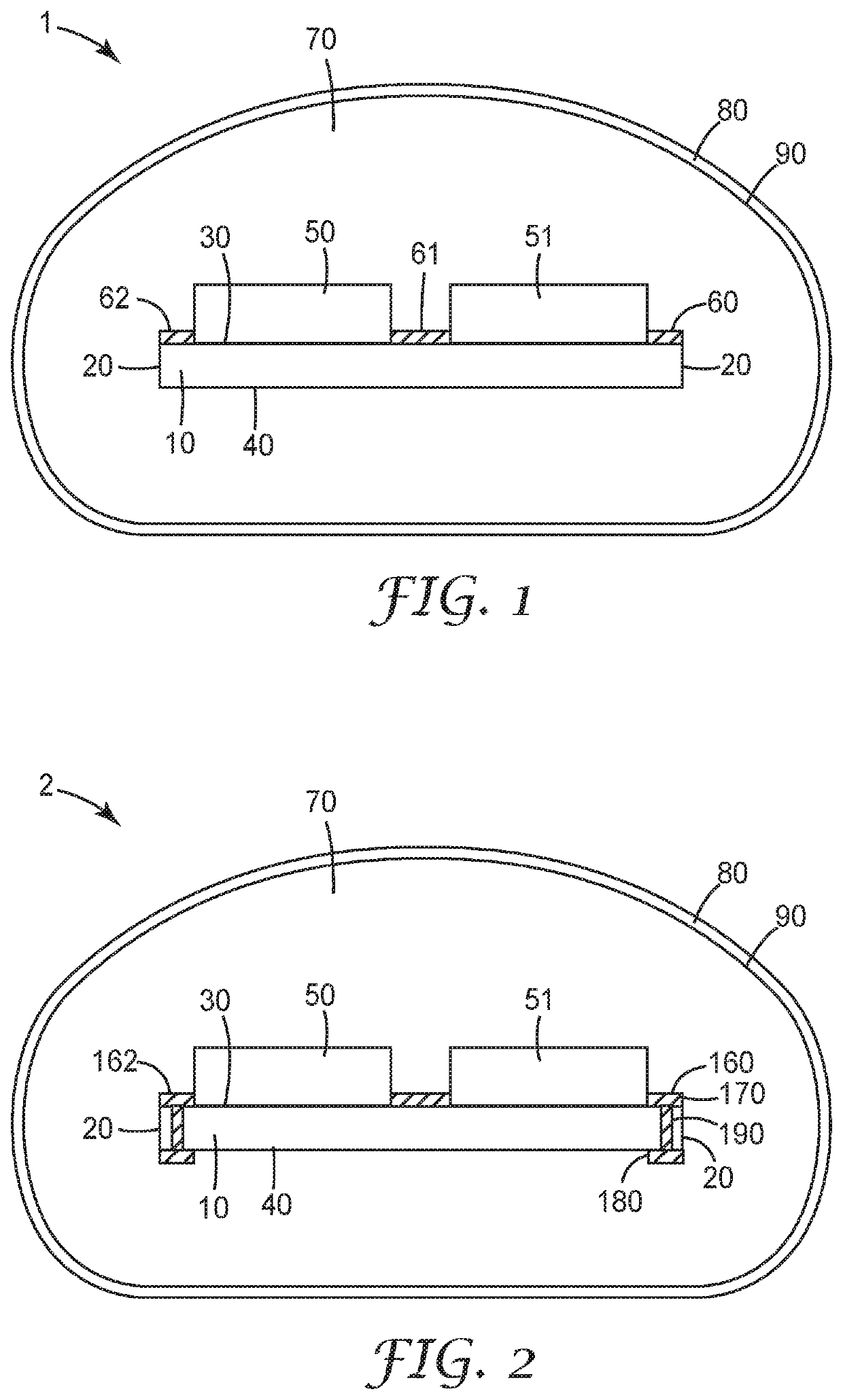
[0099]FIG. 1 illustrates, in a cross-sectional view, a first PCB assembly 1 according to the present disclosure. The first PCB assembly 1 comprises a PCB 10 having a first major surface 30 and an opposed second major surface 40. The PCB 10 is delimited by a peripheral edge 20. The PCB 10 supports a plurality of electrical and electronic components 50, 51 on its first major surface 30, of which only two are visible in FIG. 1. These components 50, 51 are discrete capacitors 50, 51, electrically connected in series with each other to form a voltage divider, or a portion of a voltage divider, for sensing a voltage of a power conductor to which the PCB assembly 1 can be electrically connected.

[0100]The discrete capacitor 51 is attached to the first surface 30, and electrically connected to other elements, by soldering at two soldering pads 60, 61. Similarly, the discrete capacitor 50 is attached to the first surface 30, and electrically connected to other elements, by soldering at two so...


PUM


Abstract

Encapsulated PCB assembly (1) for electrical connection to a high- or medium-voltage power conductor in a power distribution network of a national grid, comprising a) a PCB (10), delimited by a peripheral edge (20) and comprising a high-tension pad (60, 62) on a voltage of at least one kilovolt, b) an electrically insulating encapsulation body (70) in surface contact with, and enveloping, the high-tension pad and at least a portion of the PCB edge adjacent to the high-tension pad, c) a shielding layer (80) on an external surface (90) of the encapsulation body and for being held on electrical ground or on a low voltage to shield at least a low-voltage portion of the PCB. The high-tension pad extends to the peripheral edge of the PCB.

Description

BACKGROUND[0001]The present disclosure relates to encapsulated printed circuit boards in high-voltage or medium-voltage power distribution networks as well as to cable accessories and to networks comprising such encapsulated printed circuit boards.[0002]Sensing the voltage of a power cable in a power distribution network such as a national grid is essential to maintain the network in a stable condition. Suitable voltage sensors often use voltage dividers to sense the voltage of the cable. Certain types of these voltage dividers are electrically connected between the cable on high voltage or medium voltage (collectively referred to as “elevated voltage” herein) and electrical ground or some low voltage. Elements of these voltage dividers, such as resistors or capacitors, are normally arranged on a printed circuit board (“PCB”). Some of these elements are on elevated voltage, and so are conductive traces connecting these elements with each other, and contacts such as soldering contact...

Claims


Application Information

Patent Timeline
IPC IPC(8): H05K1/02H05K9/00H05K5/06H05K1/11G01R15/16G01R1/18
CPCH05K1/0254H05K9/0007H05K5/065H05K1/181G01R15/16G01R1/18H05K2201/09163H05K1/111H05K1/0256H05K1/0259H05K2201/09036H05K2201/10651H05K2203/1327H05K2201/10015
Inventor STOLLWERCK, GUNTHER A. J.GRAVERMANN, MARKWEICHOLD, JENSEGGERT-RICHTER, SEBASTIANSTALDER, MICHAEL H.
Owner 3M INNOVATIVE PROPERTIES CO
Why Eureka
Try Eureka