
Subway hybrid-energy multifunctional-end-integrated heat pump system and method

a multi-functional, heat pump technology, applied in the direction of waste heat machines, refrigeration components, machines, etc., can solve the problems of inability to supply waste heat in subway tunnels to a multi-purpose end, inability to liberally dispose of cooling towers, and relatively difficult drilling for ground-source heat pumps, etc., to achieve high heat utilization, solve heat accumulation in subway tunnels, and reduce the effect of heat loss

Pending Publication Date: 2022-02-03
QINGDAO TECHNOLOGICAL UNIVERSITY
View PDF3 Cites 0 Cited by
  • Summary
  • Abstract
  • Description
  • Claims
  • Application Information

AI Technical Summary

Benefits of technology

The present invention solves issues in cooling subway tunnels by combining a cooling tower and ground-source heat pump. It meets cold and heat demands in different seasons and has high heat utilization. It is environmentally-friendly, economical, and efficient.

Problems solved by technology

Due to above-ground space restrictions and urban aesthetic requirements and noise pollution and health hazards of cooling towers, cooling towers cannot be disposed liberally, and it is relatively difficult to drill for burying pipes of the ground-source heat pump.
Currently, supply of the waste heat in subway tunnels to a multi-purpose end cannot be achieved.

Method used


Image

  • Subway hybrid-energy multifunctional-end-integrated heat pump system and method
  • Subway hybrid-energy multifunctional-end-integrated heat pump system and method
  • Subway hybrid-energy multifunctional-end-integrated heat pump system and method

Examples


embodiment 1

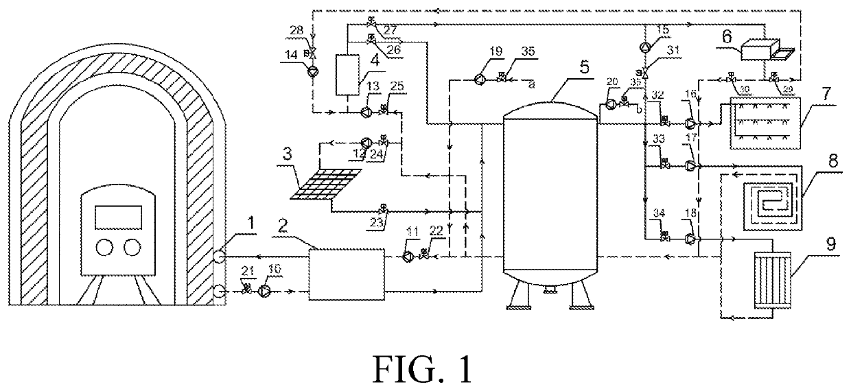
[0041]As shown in FIG. 1, a subway hybrid-energy multifunctional-end-integrated heat pump system adopting a capillary-tube heat exchanger includes: an energy end, a user end, and a hot water storage tank 5. A first energy end includes a capillary-tube front-end heat exchanger 1 laid in the surrounding rocks of a tunnel and a subway capillary-tube heat pump unit 2, a second energy end includes a solar panel 3, and a third energy end includes an air-cooled heat pump unit 4. The user end includes an air conditioner end 6, a hot water supply end 7, an underfloor heating end 8, and a radiator heating end 9. The first energy end, the second energy end, and the third energy end are connected to a water inlet of the hot water storage tank 5, and a water outlet of the hot water storage tank 5 is connected to the air conditioner end 6, the hot water supply end 7, the underfloor heating end 8, and the radiator heating end 9. Water outlets of the air conditioner end 6, the underfloor heating en...

embodiment 2

[0049]A method for supplying energy from the subway hybrid-energy multifunctional-end-integrated heat pump system of Embodiment 1 is provided.

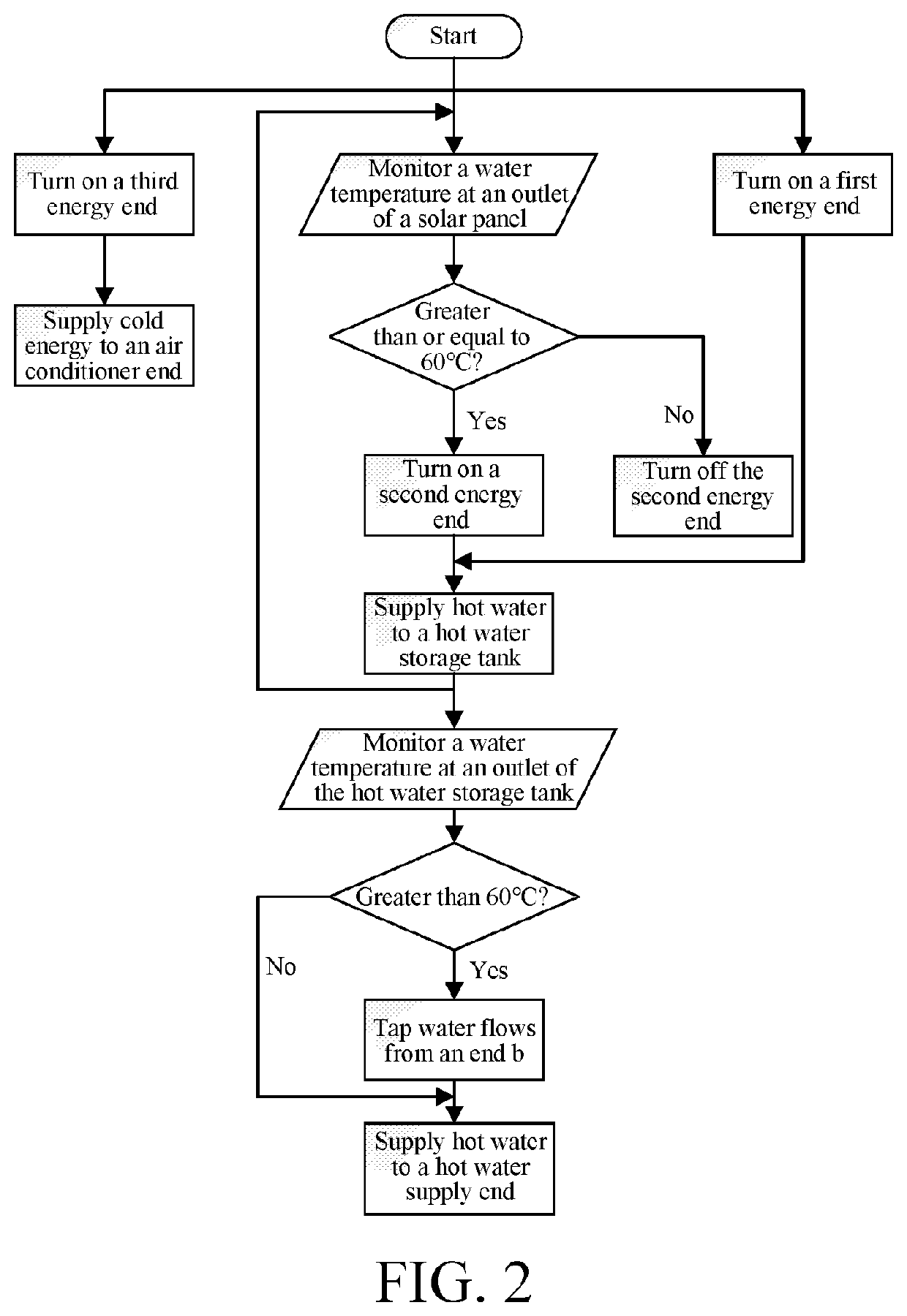
[0050]As shown in FIG. 2, an operating condition in summer is turning on a first valve 21, a second valve 22, a seventh valve 27, an eighth valve 28, a ninth valve 29, and a twelfth valve 32. A subway capillary-tube heat pump unit 2 absorbs heat from surrounding rocks and soil and air heat in a subway station through a capillary-tube front-end heat exchanger 1. The subway capillary-tube heat pump unit 2 prepares hot water while cooling a tunnel, and delivers the hot water to a hot water storage tank 5 through a pipeline. A solar panel 3 heats the hot water by means of obtained solar radiation energy. An air conditioner end 6 in the subway station needs to provide cold energy in summer. An air-cooled heat pump unit 4 supplies cold energy to the air conditioner end 6 in the subway station through a seventh valve 27, an eighth valve 28, a ninth v...


PUM


Abstract

A subway hybrid-energy multifunctional-end-integrated heat pump system includes energy and user ends and hot water tank. A first energy end includes a capillary-tube front-end heat exchanger and a subway capillary heat pump unit. A second energy end includes a solar panel. A third energy end includes an air-cooled heat pump unit. The user end includes air conditioner, hot water supply, underfloor heating, and radiator heating ends. The first, second and third energy ends connect to the hot water tank. A water outlet is connected to the air conditioner, hot water supply, underfloor heating, and radiator heating ends. Water outlets of the air conditioner, underfloor heating, and radiator heating ends are respectively connected to the first, second and third energy end through a return pipe.

Description

BACKGROUNDTechnical Field[0001]The present invention relates to the field of hybrid-energy multifunctional-end-integrated systems, and in particular, to a subway hybrid-energy multifunctional-end-integrated heat pump system adopting a capillary-tube heat exchanger and a method.Related Art[0002]The background information is provided only to increase the understanding of the overall background of the present invention, but is not necessarily regarded as an acknowledgement or in any form suggesting that the information constitutes the prior art known to a person of ordinary skill in the art.[0003]With the rapid development of economy and urbanization, the convenient and fast subway is increasingly popular. Subway construction is actively conducted in various big cities. The subway is now an indispensable vehicle for most people to go to work and out.[0004]During subway operation, due to heat generated by train braking, locomotive air conditioners, and electromechanical equipment and th...

Claims


Application Information

Patent Timeline
Patent Type & Authority Applications(United States)
IPC IPC(8): F25B27/02F25B27/00F24D3/14B61K13/00
CPCF25B27/02B61K13/00F24D3/14F25B27/002F25B30/06F28D15/04F24H4/02F24S20/40F24D3/08F24D19/1072Y02E10/40F25B2400/06F25B2339/047F24T10/10F24T50/00F28D20/0034F24D11/0242F24D2200/16Y02E10/10Y02B30/52Y02A30/60Y02B10/40Y02A30/274
Inventor HU, SONGTAOLIU, GUODANJI, YONGMINGWANG, HAIYINGTONG, LITONG, ZHEN
Owner QINGDAO TECHNOLOGICAL UNIVERSITY
Learn More