Insulating device with cooling medium line

a technology of cooling medium and insulation device, which is applied in the direction of cooling/ventilation arrangement, transportation and packaging, propulsion parts, etc., to achieve the effect of simple housing parts, low temperature value, and easy cooling and efficient operation

Pending Publication Date: 2022-02-03
ROBERT BOSCH GMBH
View PDF0 Cites 0 Cited by
  • Summary
  • Abstract
  • Description
  • Claims
  • Application Information

AI Technical Summary

Benefits of technology

[0018]The solution proposed according to the invention advantageously provides the option of simplifying housing parts for electric machines, since, as a result of the solution proposed according to the invention, the production of complicated cooling-medium channels via mold cores in cast parts or intersecting bores in cast parts can be avoided without the need for additional components such as separate connection fittings or the like, for example. As a result of the solution proposed according to the invention, the busbars routed in the insulating body of the insulting device can be cooled very easily and efficiently and kept to a low temperature value which is advantageously favorable for the ohmic resistance. As a result of the solution proposed according to the invention, it is possible to achieve a considerable reduction in the effort which is otherwise involved with regard to the cooling-medium routing. As a result of the insulating device proposed according to the invention, which has integrated cooling-medium channels, a lowering of the temperature level in the region of the busbars in the insulting body can be achieved; furthermore, as a result of the solution proposed according to the invention, efficient and reliable electrical insulation of the busbars with respect to one another can, in particular, be achieved. In contrast to previously applied solutions when using pipe elbows and the like which have to be subsequently insulated, the solution proposed according to the invention enables the number of components to be reduced, seals to be omitted and, in particular, a leak-free cooling-medium routing to be ensured.

Problems solved by technology

Since the connection of the internal cooling-water routing and the desired connection direction of the cooling-water hoses often call for unfavorably curved feed regions which can only be produced with great difficulty in a casting technique, they are generally formed with fitted tubes made from plastic or metal.

Method used


Image

  • Insulating device with cooling medium line
  • Insulating device with cooling medium line
  • Insulating device with cooling medium line

Examples


first embodiment

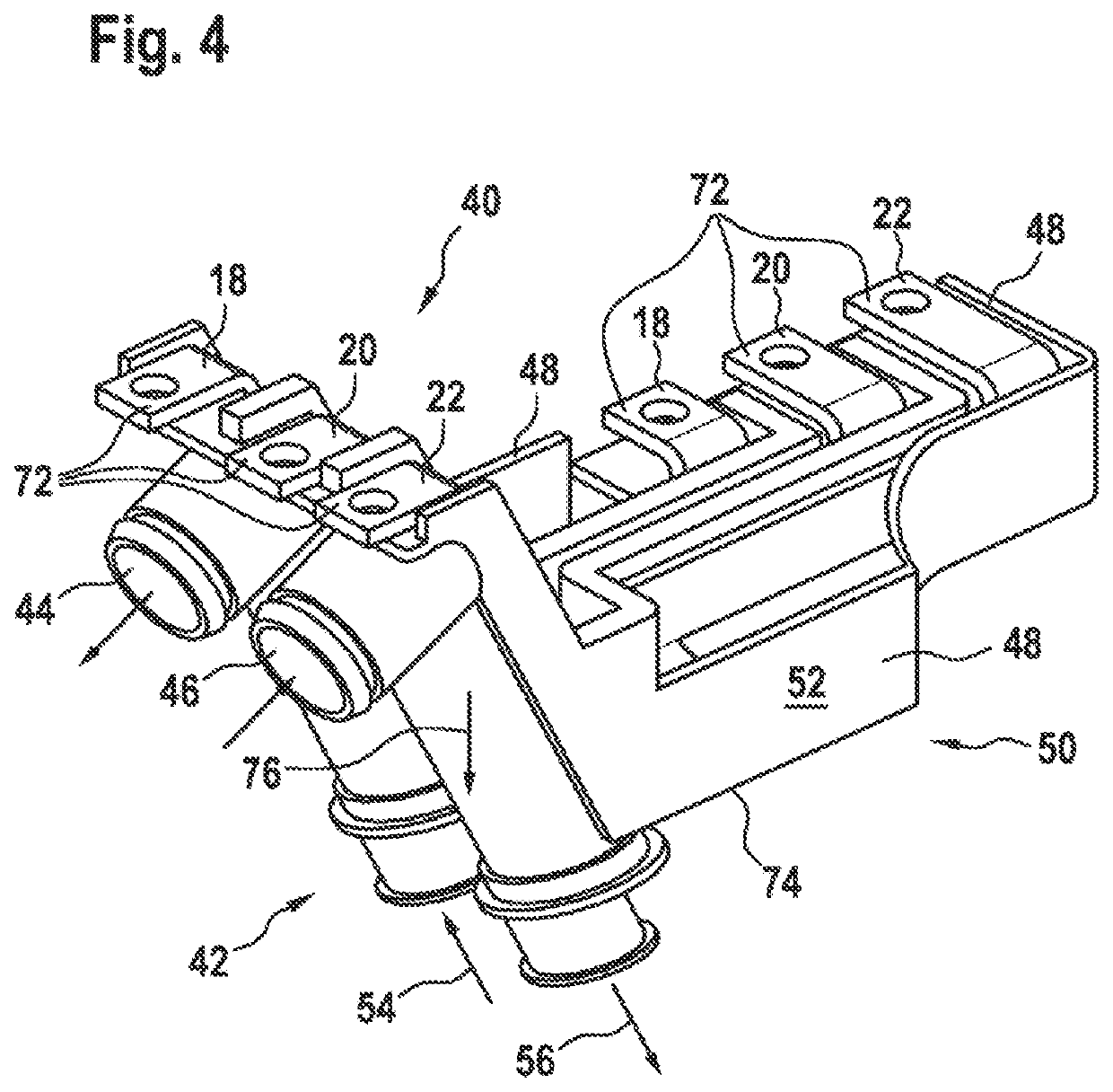
[0032]FIG. 4 shows a first embodiment variant of the insulating device proposed according to the invention, with integrated cooling-medium channels.

[0033]The illustration according to FIG. 4 reveals that an insulating body 74, in which the first busbar 18, the second busbar 20 and the third busbar 22 are received such that they are insulated with respect to one another, is manufactured from a first plastic material 52, for example. In this illustration according to FIG. 4, this refers to an insulating body 74 which is produced from a first plastic material 52. For manufacturing reasons with regard to the first channel 44 and the second channel 46, the plastic injection molding method comes into consideration for the production of the insulating body 47. The first plastic material 52 is, for example, an electrically insulating plastic material optimized for the best possible heat conduction, such as Luvocom 1-8259 or Tecacomp PA 66 TC 3923, for example.

embodiment 50

[0034]The illustration according to FIG. 4 reveals that the insulating body 74 of the insulating device 40 is formed in a single-part embodiment 50. The insulating body 74 is preferably manufactured in an operating procedure within the plastic injection molding process. The respective insulating webs 34 surrounded by a border 48 can also be manufactured in the plastic injection molding process. The first busbar 18 is electrically insulated from the second busbar 20 and the second busbar 20 is electrically insulated from the third busbar 22 by the insulating webs 34 which pass through the interior of the insulating body 74. The first, second and third busbars 18, 20, 22 comprise respective connection regions 72, which can be provided with a circular opening or the like, for example.

[0035]It can furthermore be seen from FIG. 4 that the first channel 44 and the second channel 46 run substantially in the vertical direction 76 at the end face 42 of the insulating body 74. An inflow 54 is...


PUM

PropertyMeasurementUnit
electrically insulatingaaaaaaaaaa
insulatingaaaaaaaaaa
heat-conductingaaaaaaaaaa

Abstract

The invention relates to an insulating device (40) having integrated cooling medium channels (44, 46), comprising an insulating body (74) made of a plastic material (52, 60), in which conductor rails (18, 20, 22) are accommodated. The cooling medium channels (44, 46) are integrated into the plastic material (52, 60) of the insulating body (74).

Description

BACKGROUND OF THE INVENTION[0001]The invention relates to an insulating device with a cooling-medium line, which is used to dissipate heat losses of a stator of an electric machine. The invention furthermore relates to the use of the insulating device in an electric machine of a vehicle having at least one electric machine.[0002]DE 10 2012 021 600 A1 relates to an electric motor. The electric motor comprises a housing, with a stator, a rotor and a rotary transmitter. The rotary transmitter has a primary-side first device with a primary winding and a secondary-side second device with a secondary winding. The housing has a first receptacle for the positioning of the primary-side first device. The primary-side first device comprises a number of first fastening points for force-fitting and / or form-fitting fastening on the housing. The rotor comprises a second receptacle for the positioning of the secondary-side second device, wherein the secondary-side second device has a number of seco...

Claims


Application Information

Patent Timeline
Patent Type & Authority Applications(United States)
IPC IPC(8): H02K9/197H02K5/20H02K5/22H02K5/15B60K11/02
CPCH02K9/197H02K5/20B60K11/02H02K5/15H02K5/225H02K5/22
Inventor ZWEIGLE, PETERRIEDL, JOHANNESBREINLINGER, PHILIPPWURSTER, HEIKO
Owner ROBERT BOSCH GMBH
Why Eureka
Try Eureka