Cast strip manufacturing method

a manufacturing method and casting strip technology, applied in the field of casting strip manufacturing methods, can solve the problems of large deviation in inability to start casting stably, and inability to reduce the solidified shell at the drum kiss point in some cases, so as to achieve stab casting, reduce the breakage of the cast strip, and reduce the thickness of the solidified shell.

Active Publication Date: 2022-02-17
NIPPON STEEL CORP
View PDF0 Cites 0 Cited by
  • Summary
  • Abstract
  • Description
  • Claims
  • Application Information

AI Technical Summary

Benefits of technology

[0019]According to the cast strip manufacturing methods described in (1) and (2), parallel control is not performed during a period when a thermal expansion portion of a cooling drum, which is formed at the start of casting, is in contact with a side weir, and the one end side and the another end side in the rotation axis direction of the pair of cooling drums are pressed with the same pressure. Therefore, even if the base metal is caught between the cooling drums, the solidified shells can be sufficiently reduced at a drum kiss point, and formation of an unsolidified portion in a central portion of the thickness of the cast strip is suppressed. As a result, breakage of the cast strip is suppressed, and the casting can be started stably.
[0020]Furthermore, in the first step, since the one end side and the another end side in the rotation axis direction of the pair of cooling drums are pressed with the first pressure, which presses the one end side and the another end side with the same pressure, in the direction in which the pair of cooling drums come close to each other, the thickened portion can be passed between the cooling drums relatively stably.
[0021]Furthermore, in the second step, since the cooling drums are pressed with the second pressure higher than the first pressure, the solidified shells can be sufficiently reduced at the drum kiss point, and the formation of the unsolidified portion in the central portion of the thickness of the cast strip can be suppressed.
[0022]In particular, according to the cast strip manufacturing method described in (2), the period until the cooling drums make two or more rotations is set as the second step, so that the one end side and the another end side in the rotation axis direction of the pair of cooling drums are pressed with the same pressure even if the above-described thermal expansion portion remains until the second rotation. Therefore, the solidified shells can be sufficiently reduced at the drum kiss point, and the formation of the unsolidified portion in the central portion of the thickness of the cast strip can be suppressed. As a result, the breakage of the cast strip can be suppressed, and the casting can be started stably.
[0023]As described above, according to the present invention, it is possible to provide a cast strip manufacturing method capable of suppressing breakage of a cast strip and starting casting stably in a twin-drum type continuous casting apparatus.

Problems solved by technology

Therefore, in an unsteady state immediately after the start of casting, deviation in the thickness of the solidified shells is large, and when the pressure control is performed as in Patent Document 1, the solidified shells cannot be sufficiently reduced at the drum kiss point in some cases.
In this case, an unsolidified portion is formed in a central portion of the thickness of the cast strip, the surface temperature of the cast strip is relatively high, and the strength is insufficient, which causes breakage or the like of the cast strip, and the casting cannot be started stably.
In particular, a hump-shaped locally thickened portion (hereinafter, may be referred to as a thickened portion) is formed on the cast strip immediately after the start of casting because the solidified shells grow with the cooling drums stopped, and the casting is unstable when this thickened portion passes through the drum kiss point.

Method used


Image

  • Cast strip manufacturing method
  • Cast strip manufacturing method
  • Cast strip manufacturing method

Examples


examples

[0085]Results of experiments conducted to confirm effects of the present invention will be described below.

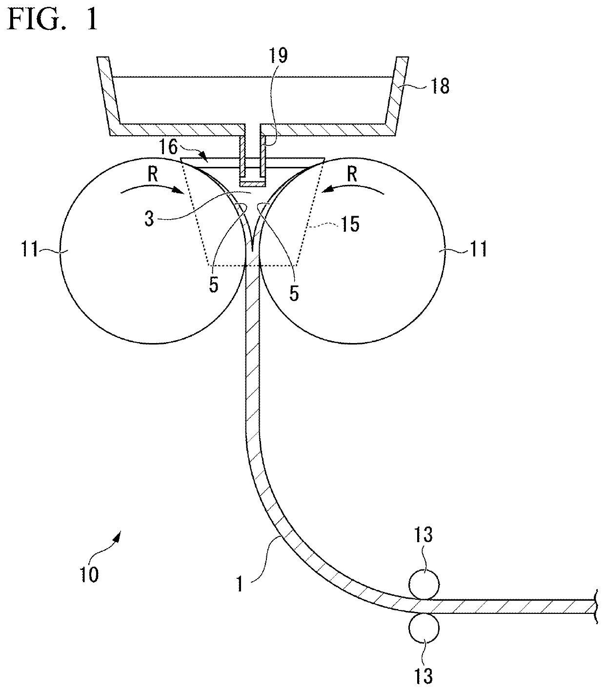
[0086]A cast strip made of carbon steel having a carbon content of 0.05 mass % was manufactured by use of the twin-drum type continuous casting apparatus illustrated in FIG. 1.

[0087]Here, the diameter of the cooling drum was set to 600 mm, and the width of the cooling drum was set to 400 mm. In addition, the thickness of the cast strip in steady casting was set to 2.0 mm.

[0088]In Example 1 of the present invention, switching from the first step to the second step was performed when the number of rotations of the cooling drum was 0.1 rotations, and switching from the second step to the third step was performed when the number of rotations of the cooling drum was 1.3 rotations.

[0089]In Example 2 of the present invention, the switching from the first step to the second step was performed when the number of rotations of the cooling drum was 0.1 rotations, and the switching from the...


PUM

PropertyMeasurementUnit
thicknessaaaaaaaaaa
thicknessaaaaaaaaaa
thicknessaaaaaaaaaa

Abstract

In this cast strip manufacturing method, in a first step, one end side and another end side in a rotation axis direction of a pair of cooling drums are pressed with a first pressure in a direction in which the cooling drums come close to each other, in a second step, the one end side and the another end side in the rotation axis direction of the cooling drums are pressed with a second pressure, which is higher than the first pressure, in the direction in which the cooling drums come close to each other, and in a third step, pressure control is performed so that a total value of reaction forces on the one end side and the another end side in the rotation axis direction of the cooling drums is set to a predetermined value, and rotation axes of the cooling drums are held in parallel.

Description

TECHNICAL FIELD OF THE INVENTION[0001]The present invention relates to a cast strip manufacturing method in which molten metal is supplied to a molten metal reservoir formed by a pair of cooling drums and a pair of side weirs to manufacture a cast strip.RELATED ART[0002]As a manufacturing method for a thin metal cast strip (hereinafter, may be referred to as a cast strip), for example, as shown in Patent Documents 1 and 2, there is provided a manufacturing method using a twin-drum type continuous casting apparatus including a cooling drum having a water-cooled structure inside. In such a manufacturing method, molten metal is supplied to a molten metal reservoir formed between a pair of cooling drums that rotate, and solidified shells formed and grown on peripheral surfaces of the pair of cooling drums are joined to each other at a drum kiss point and reduced to manufacture a cast strip having a predetermined thickness. Such a manufacturing method using the twin-drum type continuous ...

Claims


Application Information

Patent Timeline
Patent Type & Authority Applications(United States)
IPC IPC(8): B22D11/06B22D11/22
CPCB22D11/0682B22D11/22B22D11/0622B22D11/06B22D11/16B22D11/0625B22D11/0651B22D11/201
Inventor ARAIMIYAZAKI, MASAFUMIYOSHIDA, NAOTSUGU
Owner NIPPON STEEL CORP
Why Eureka
Try Eureka