Bioinert pipe and liquid chromatograph
a technology of liquid chromatograph and bioinert pipe, which is applied in the field of bioinert pipe to achieve the effects of reducing the risk of flange breakage, maintaining the required pressure resistance performance, and improving the durability of sealing performan
- Summary
- Abstract
- Description
- Claims
- Application Information
AI Technical Summary
Benefits of technology
Problems solved by technology
Method used
Image
Examples
first embodiment
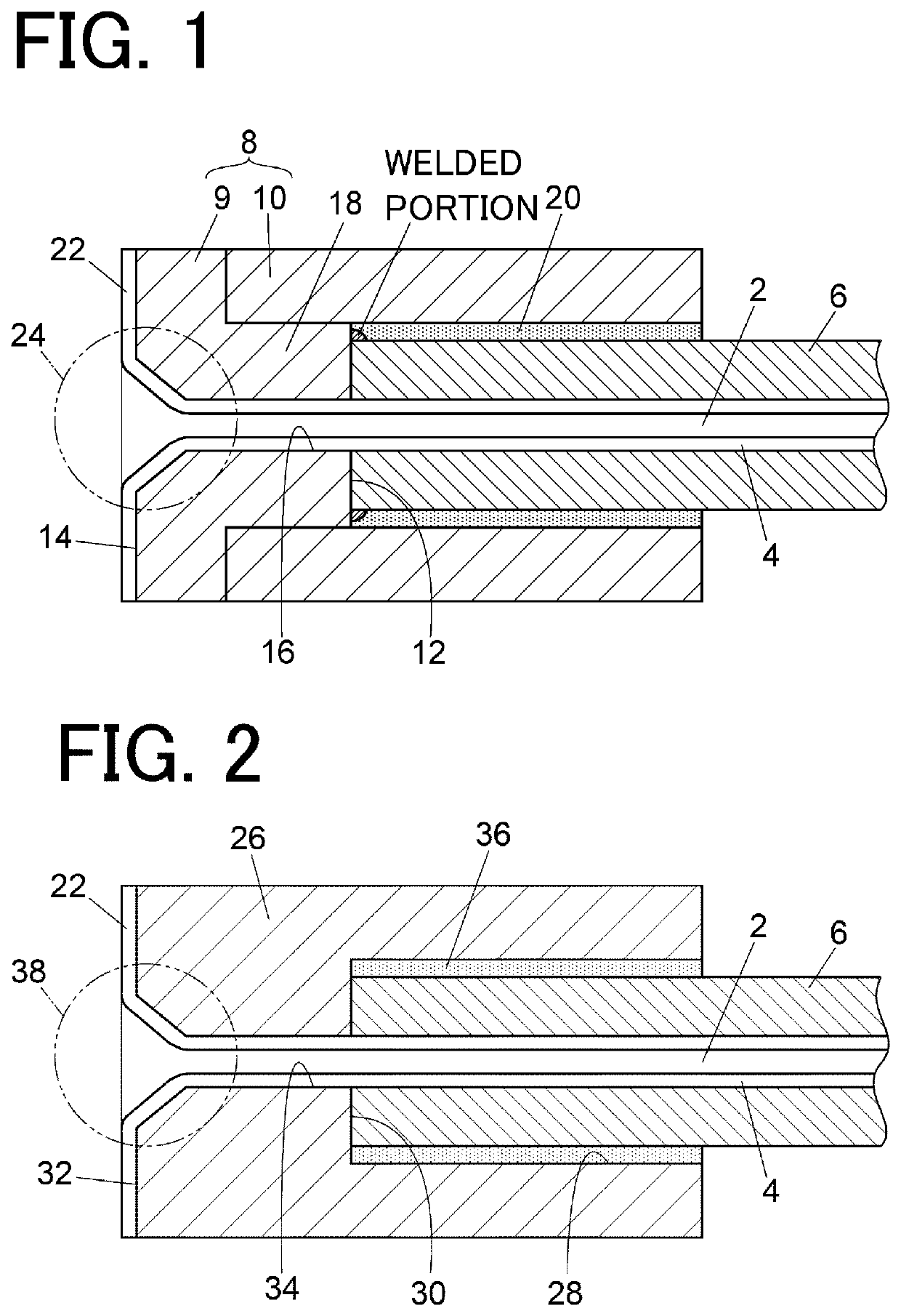
[0017]FIG. 1 is an end portion cross-sectional view of the bioinert pipe.
[0018]The bioinert pipe of the present embodiment has a structure in which an inner wall surface of a flow path 2 for allowing a mobile phase to flow is formed of a resin tube 4, and an outer peripheral surface of the resin tube 4 is covered with a metal tube 6. As to the size of the resin tube 4 and the metal tube 6, for example, the resin tube 4 has an inner diameter of 0.1 mm and an outer diameter of 0.36 mm, and the metal tube 6 has an inner diameter of 0.4 mm and an outer diameter of 0.76 mm. In another mode, for example, the resin tube 4 has an inner diameter of 0.3 mm and an outer diameter of 0.46 mm, and the metal tube 6 has an inner diameter of 0.5 mm and an outer diameter of 0.76 mm.
[0019]An end portion extension member 8 is attached to an end portion of the metal tube 6. The end portion extension member 8 is provided to extend an end portion of the metal tube 6 in a direction in which an end surface ...
second embodiment
[0025]FIG. 2 is an end portion cross-sectional view of the bioinert pipe.
[0026]The second embodiment is different from the first embodiment in that an end portion extension member 26 attached to an end portion of the metal tube 6 is realized by an integrated sleeve. The end portion extension member 26 includes a recess 28 into which the metal tube 6 is inserted, and a first surface 30 facing and in contact with an end surface of the metal tube 6 is provided at the bottom of the recess 28. A surface of an outer surface of the end portion extension member 26, the surface being located on the side opposite to a surface provided with the recess 28, is a second surface 32 for supporting the flange portion 22 forming a sealing structure, and is provided with a through hole 34 passing to the second surface 32 from the first surface 30. The end portion extension member 26 is brazed with the metal tube 6. A layer 36 of a poured brazing material is formed in a gap between an outer peripheral ...
PUM
| Property | Measurement | Unit |
|---|---|---|
| outer diameter | aaaaa | aaaaa |
| outer diameter | aaaaa | aaaaa |
| outer diameter | aaaaa | aaaaa |
Abstract
Description
Claims
Application Information
 - R&D
- Intellectual Property
- Life Sciences
- Materials
- Tech Scout
- Unparalleled Data Quality
- Higher Quality Content
- 60% Fewer Hallucinations
Browse by: Latest US Patents, China's latest patents, Technical Efficacy Thesaurus, Application Domain, Technology Topic, Popular Technical Reports.
© 2025 PatSnap. All rights reserved.Legal|Privacy policy|Modern Slavery Act Transparency Statement|Sitemap|About US| Contact US: help@patsnap.com

