
Calibration method and device for dental implant navigation surgery, and tracking method and device for dental implant navigation surgery

Pending Publication Date: 2022-02-24
BEIJING YAKEBOT TECH CO LTD
View PDF0 Cites 0 Cited by
  • Summary
  • Abstract
  • Description
  • Claims
  • Application Information

AI Technical Summary

Benefits of technology

The patent provides a solution for improving the accuracy and reducing trauma during dental implant surgery by eliminating the need for marker points. The methods involve using visual markers on both the surgical area and the scanning device for calibration and tracking of surgical instruments. This allows for real-time position tracking of the surgical instruments without implanting a marker point into the patient's body. Overall, the methods provide better accuracy and efficiency during dental implant surgery.

Problems solved by technology

The failure rate of the implant surgery is high due to factors such as indirect vision environment of the oral cavity, narrow operating space and lack of experience of dentists.
However, if the anatomical marker points are used for registration, it will bring about the problem of low registration precision; and if the artificial marker points are used for registration, the artificial marker points need to be implanted into the patient's alveolar process or jaw, which may cause unnecessary trauma or even infection.

Method used


Image

  • Calibration method and device for dental implant navigation surgery, and tracking method and device for dental implant navigation surgery
  • Calibration method and device for dental implant navigation surgery, and tracking method and device for dental implant navigation surgery
  • Calibration method and device for dental implant navigation surgery, and tracking method and device for dental implant navigation surgery

Examples


Embodiment Construction

[0032]In order to illustrate the objectives, technical solutions and advantages of the embodiments of the present application more clearly, the technical solutions in the embodiments of the present application will be described clearly and completely in conjunction with the accompanying drawings in the embodiments of the present application. Obviously, the described embodiments are part of the embodiments of the present application, rather than all of the embodiments. All other embodiments obtained by a person of ordinary skill in the art based on the embodiments of the present application without any creative effort fall within the protection scope of the present application.

[0033]In a traditional oral implant navigation surgery, the mapping relationship between the virtual image space and the visual space is determined by a marker point registration method, so as to tracking the spatial position of a surgical instrument in real time. When anatomical marker points are used for regi...


PUM


Abstract

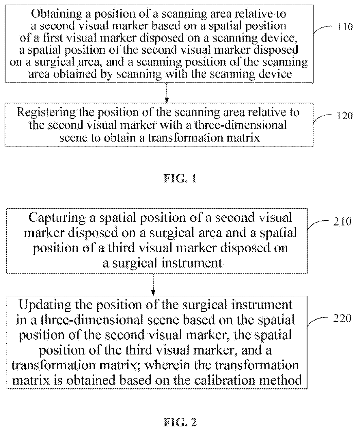
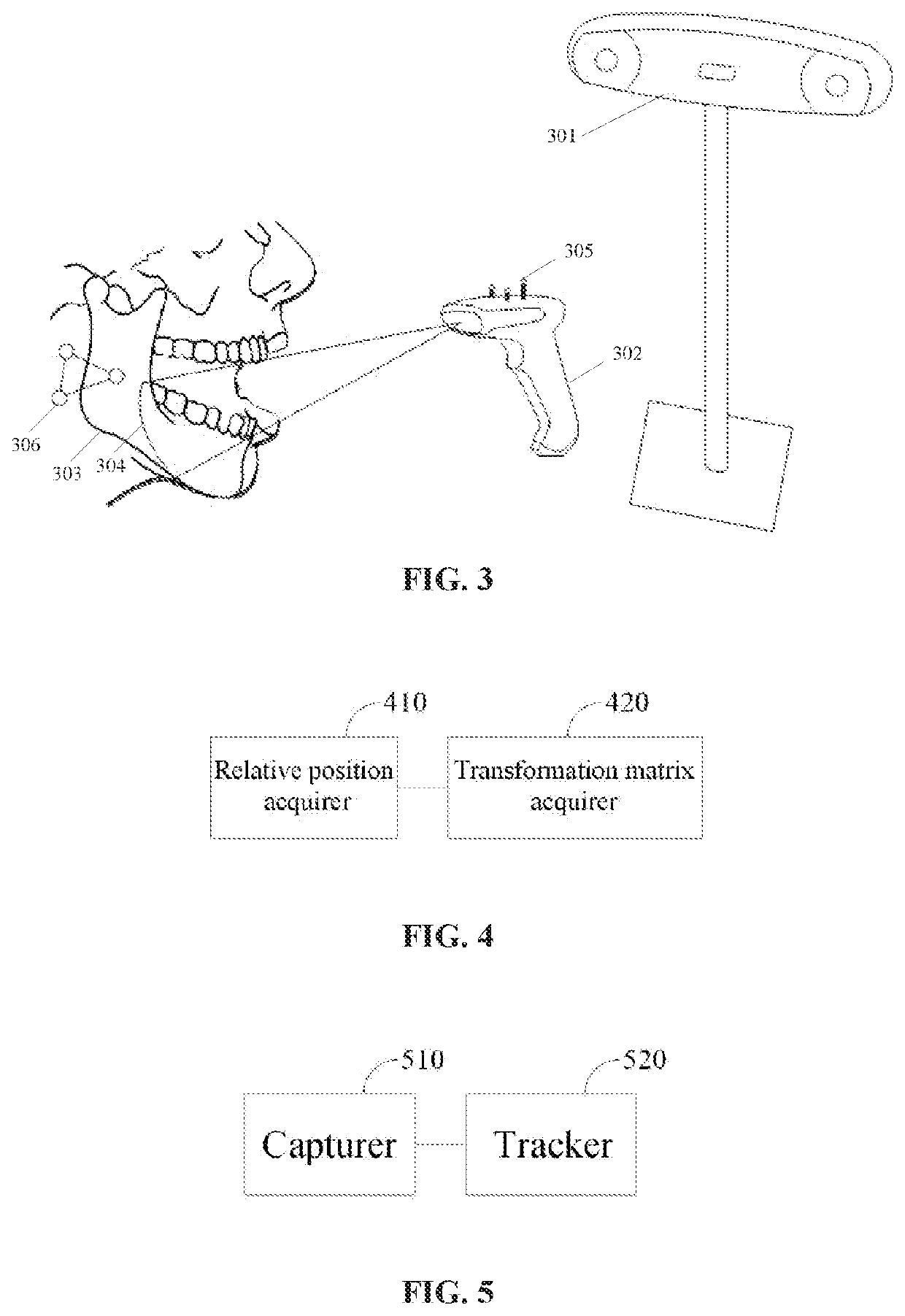
Embodiments of the present application provide a calibration method and device for dental implant navigation surgery, and a tracking method and device for dental implant navigation surgery. The calibration method comprises: (110) obtaining a position of a scanning area (304) relative to a second visual marker (306) based on a spatial position of a first visual marker (305) disposed on a scanning device (302), a spatial position of the second visual marker (306) disposed on a surgical area (303), and a scanning position of the scanning area (304) obtained by scanning with the scanning device (302); and (120) registering the position of the scanning area (304) relative to the second visual marker (306) with a three-dimensional scene to obtain a transformation matrix, and applying the transformation matrix to the tracking of a surgical instrument. Therefore, the position change of a surgical instrument may be reflected in real time in the three-dimensional scene without implanting a marker point into the body of a patient, even if the patient's head moves during the surgery, thereby accurately tracking the surgical instrument in real time.

Description

CROSS-REFERENCE TO RELATED APPLICATION[0001]The present application claims priority to Chinese patent application No. 201811602134.5 filed on Dec. 26, 2018, entitled “Calibration Method and Device for Dental Implant Navigation Surgery, and Tracking Method and Device for Dental Implant Navigation Surgery,” which is hereby incorporated by reference in its entirety.FIELD OF TECHNOLOGY[0002]The embodiments of the present application relate to the technical field of medical treatment, in particular to a calibration method and a calibration device for dental implant navigation surgery, and a tracking method and a tracking device for dental implant navigation surgery.BACKGROUND[0003]In recent years, with the promotion of oral implant technology in the clinic and the improvement of people's demand for oral health, more and more patients choose implant restoration treatment for missing teeth. An oral implant surgery is a precise operation under local anesthesia in a narrow space. The failure...

Claims


Application Information

Patent Timeline
IPC IPC(8): A61B34/20A61C8/00A61B90/00
CPCA61B34/20A61C8/0089A61B2560/0223A61B2034/2055A61B2090/3937A61B90/39A61C1/084A61C9/0053A61C9/0046A61B2017/00725A61B2090/3983A61B34/10A61B90/36A61B2034/2068A61B2034/2046A61B2034/108A61B2034/107A61B2034/105A61B2090/364G06T7/30G06T7/70
Inventor WANG, LIFENG
Owner BEIJING YAKEBOT TECH CO LTD
Learn More