Adjustment mechanism and projection device

a technology of adjustment mechanism and projection device, which is applied in the direction of projectors, instruments, optics, etc., can solve the problems of increasing assembly time, reducing product yield, and wear of parts, so as to improve assembly process and reduce costs.

Pending Publication Date: 2022-03-03
CORETRONIC
View PDF4 Cites 2 Cited by
  • Summary
  • Abstract
  • Description
  • Claims
  • Application Information

AI Technical Summary

Benefits of technology

[0006]The invention provides an adjustment mechanism, which is adapted to fix an

Problems solved by technology

However, in the known adjustment mechanism, the spring may be ejected during the assembly process, causing damage or contamination, and ultimately causing the

Method used


Image

  • Adjustment mechanism and projection device
  • Adjustment mechanism and projection device
  • Adjustment mechanism and projection device

Examples


Embodiment Construction

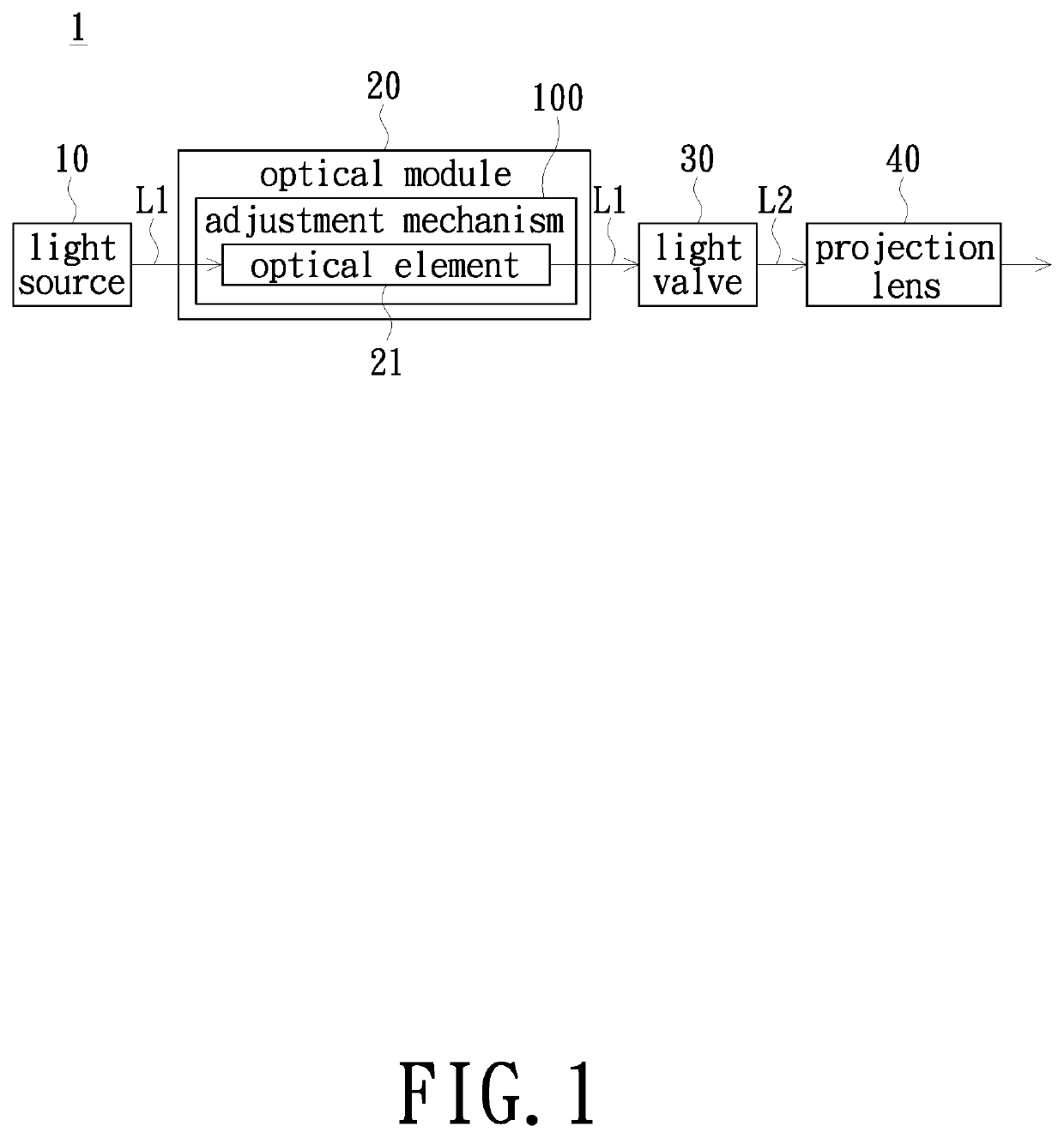
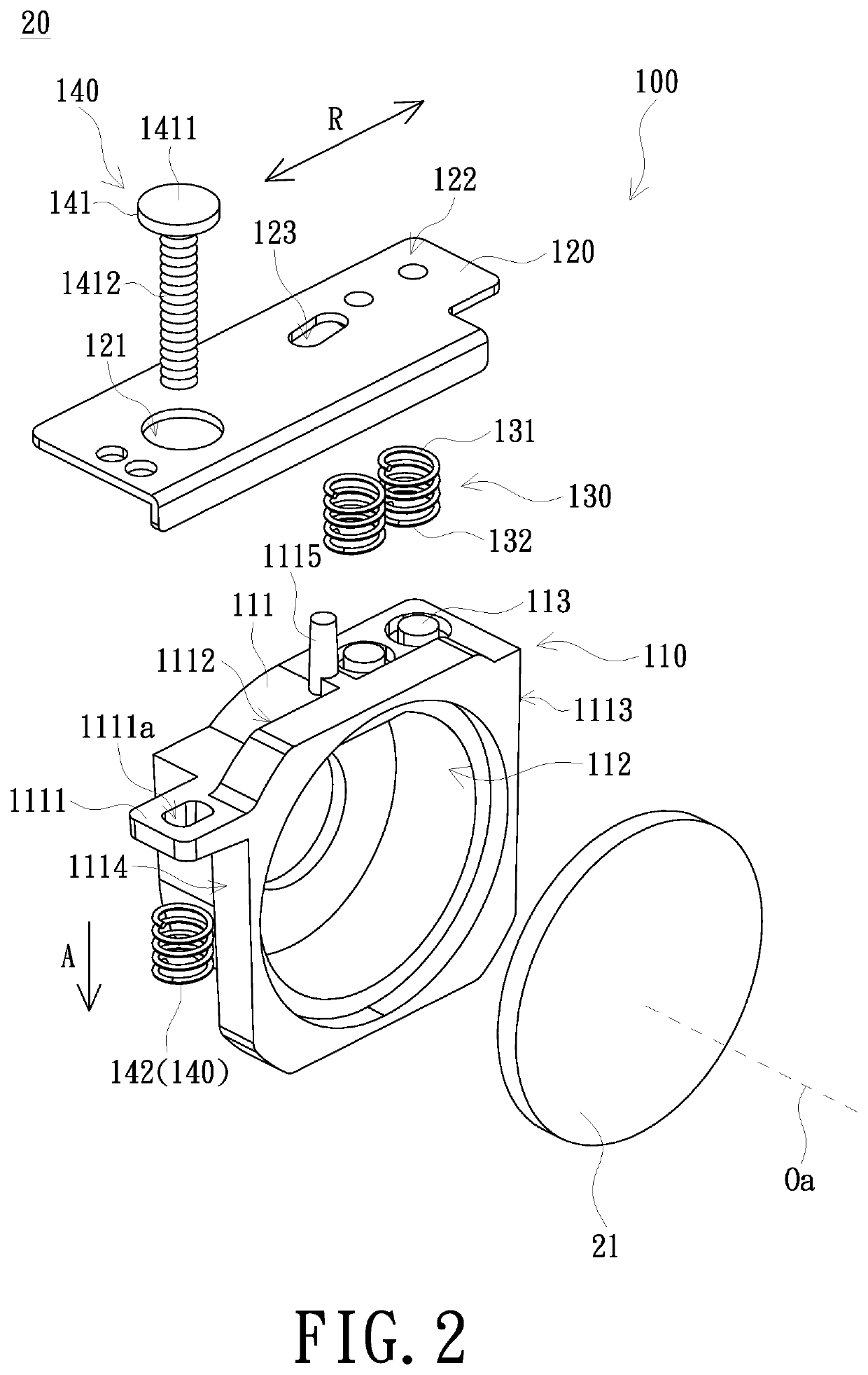
[0019]In the following detailed description of the preferred embodiments, reference is made to the accompanying drawings which form a part hereof, and in which is shown by way of illustration specific embodiments in which the invention may be practiced. In this regard, directional terminology, such as “top”, “bottom”, “front”, “back”, etc., is used with reference to the orientation of the Figure(s) being described. The components of the invention can be positioned in a number of different orientations. As such, the directional terminology is used for purposes of illustration and is in no way limiting. On the other hand, the drawings are only schematic and the sizes of components may be exaggerated for clarity. It is to be understood that other embodiments may be utilized and structural changes may be made without departing from the scope of the invention. Also, it is to be understood that the phraseology and terminology used herein are for the purpose of description and should not b...


PUM


Abstract

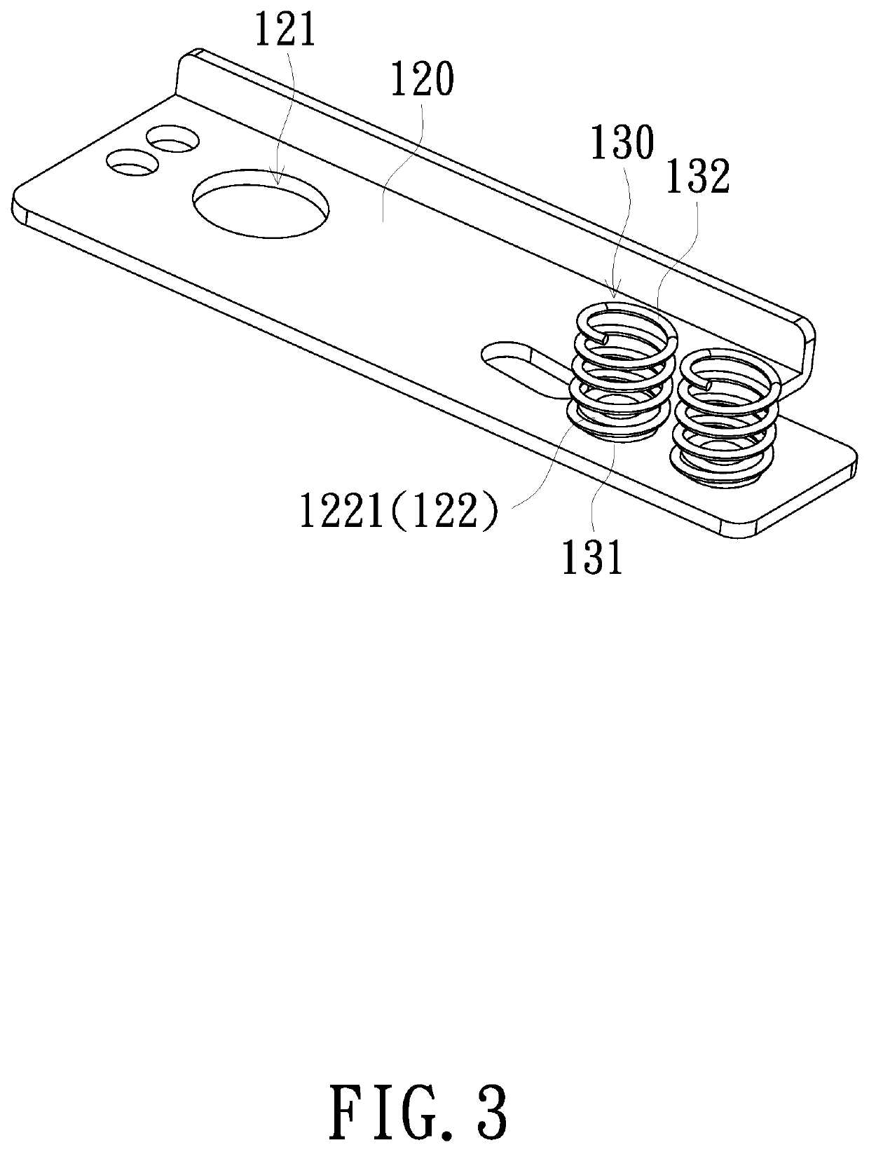
An adjustment mechanism is adapted to fix and adjust an optical element. The adjustment mechanism includes a housing, a fixing member and an elastic member. The housing is adapted for accommodate the optical element, and has a side wall, and the side wall has a locking portion protruding outward. The fixing member is disposed beside the side wall. The fixing member has a joint portion. The elastic member is disposed between the fixing member and the housing. The elastic member has a first end and a second end relative to the first end. The first end is combined with the joint portion, and the second end is abutted against the side wall. The adjusting part passes through the opening and connects with the locking portion. A projection device is further provided. The adjustment mechanism and the projection device of the invention may improve the assembly process and reduce costs.

Description

CROSS-REFERENCE TO RELATED APPLICATION[0001]This application claims the priority benefit of China application 202021896866.2, filed on 2020 Sep. 3. The entirety of the above-mentioned patent application is hereby incorporated by reference herein and made a part of this specification.FIELD OF THE INVENTION[0002]The invention relates to an adjustment mechanism, and more particularly to an adjustment mechanism for optical elements and a projection device using the adjustment mechanism.BACKGROUND OF THE INVENTION[0003]The type of light source used in the projection device has evolved from ultra-high pressure mercury lamp (UHP lamp), light emitting diode (LED) to laser diode (LD) with the market demand for brightness, color saturation, service life, non-toxic environmental protection and the like of the projection device.[0004]Various optical elements are disposed in the projection device to converge, split or transmit light. When disposing the optical element, the sheet metal, spring an...

Claims


Application Information

Patent Timeline
IPC IPC(8): G03B21/14
CPCG03B21/142
Inventor TSO, CHIA-CHING
Owner CORETRONIC
Why Eureka
Try Eureka