

Susceptor of a CVD reactor
- Summary
- Abstract
- Description
- Claims
- Application Information
AI Technical Summary
Benefits of technology
Problems solved by technology
Method used
Image

Examples
Embodiment Construction
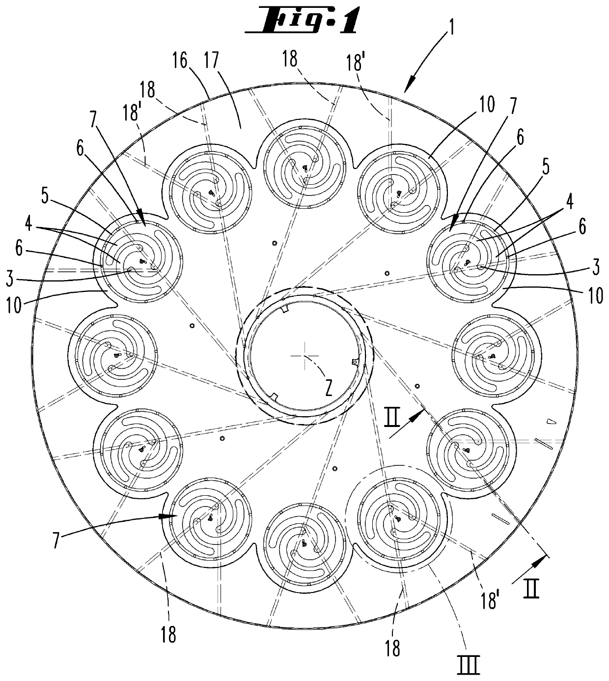
[0027]The inventive susceptor 1 is used in a CVD reactor, in particular an MOCVD reactor, as illustrated in FIG. 8. In a housing 23, which can be evacuated, is located a process chamber, into which process gases are fed by means of a gas inlet unit 22. The process gases are fed into a center of the process chamber, the floor of which is formed by a broad surface of the susceptor 1 facing upwards. The susceptor can have the shape illustrated in FIG. 1, that is to say, it can have, for example, twelve bearing surfaces 7, arranged at regular intervals around the center, wherein each bearing surface 7 is designed as a pocket. The pocket can consist of a recess in the susceptor 1 made of graphite. However, it is also possible to form the pockets from cover plates, which form circular openings.
[0028]The susceptor 1 is heated from below by means of a heating device 21, such that heat flows through the susceptor 1, into the substrate holder 2, through the substrate holder 2 to a substrate 1...
PUM
| Property | Measurement | Unit |
|---|---|---|
| Diameter | aaaaa | aaaaa |
| Length | aaaaa | aaaaa |
| Length | aaaaa | aaaaa |
Abstract
Description
Claims
Application Information