RFID label and RFID tag

Pending Publication Date: 2022-03-10
SATO HLDG CORP
View PDF0 Cites 1 Cited by
  • Summary
  • Abstract
  • Description
  • Claims
  • Application Information

AI Technical Summary

Benefits of technology

The present invention relates to an RFID label and an RFID tag with an antenna that is separated at a tear off line. The invention provides a way to maintain good RFID performance even if the tear off line and the antenna pattern intersect with each other. By forming the tear off line in the wide part of the dipole antenna and in a way that doesn't cut it completely, the arrangement and size of the antenna pattern are less restricted. This results in better RFID performance.

Problems solved by technology

With the above-described RFID medium formed with the tear off line, if the tear off line is formed so as to intersect with an antenna pattern, there is a risk in that the antenna pattern is cut off.
Thus, as the length of the antenna pattern is shortened, the communication range of the antenna is also reduced, and as a result, a deterioration of an antenna performance is caused.

Method used


Image

  • RFID label and RFID tag
  • RFID label and RFID tag
  • RFID label and RFID tag

Examples


first embodiment

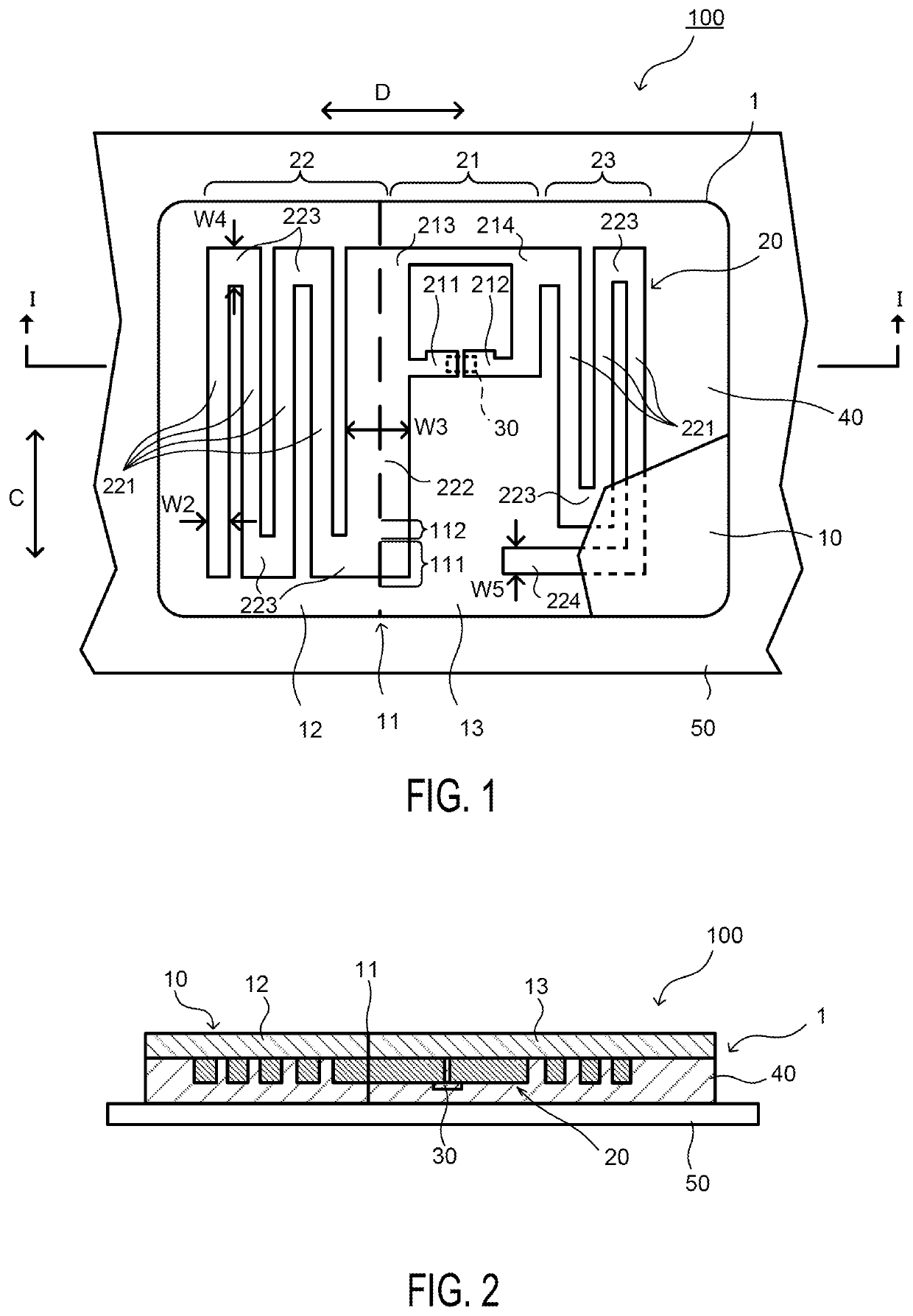
[0022]An RFID label 100 according to a first embodiment of the present invention will be described.

[0023]FIG. 1 is a schematic plan view showing the RFID label 100 according to the first embodiment with a part thereof cut out, and FIG. 2 is a sectional view taken along a line I-I shown in the RFID label 100 according to the first embodiment of the present invention.

[0024]The RFID label 100 is provided with an RFID inlay 1, an adhesive agent 40 that is overlaid on the RFID inlay 1, and a separator 50 that is temporarily adhered to the adhesive agent 40, and the RFID label 100 is the label that can be separated along a tear off line 11.

[0025]In this embodiment, the RFID inlay is formed by joining an IC chip having an RFID specification to an antenna pattern that is formed on a surface of a substrate (such as a paper, a film, and so forth) with an anisotropically conductive paste.

[0026]In this embodiment, the antenna pattern is a dipole antenna pattern.

[0027]The RFID inlay 1 has a subs...

second embodiment

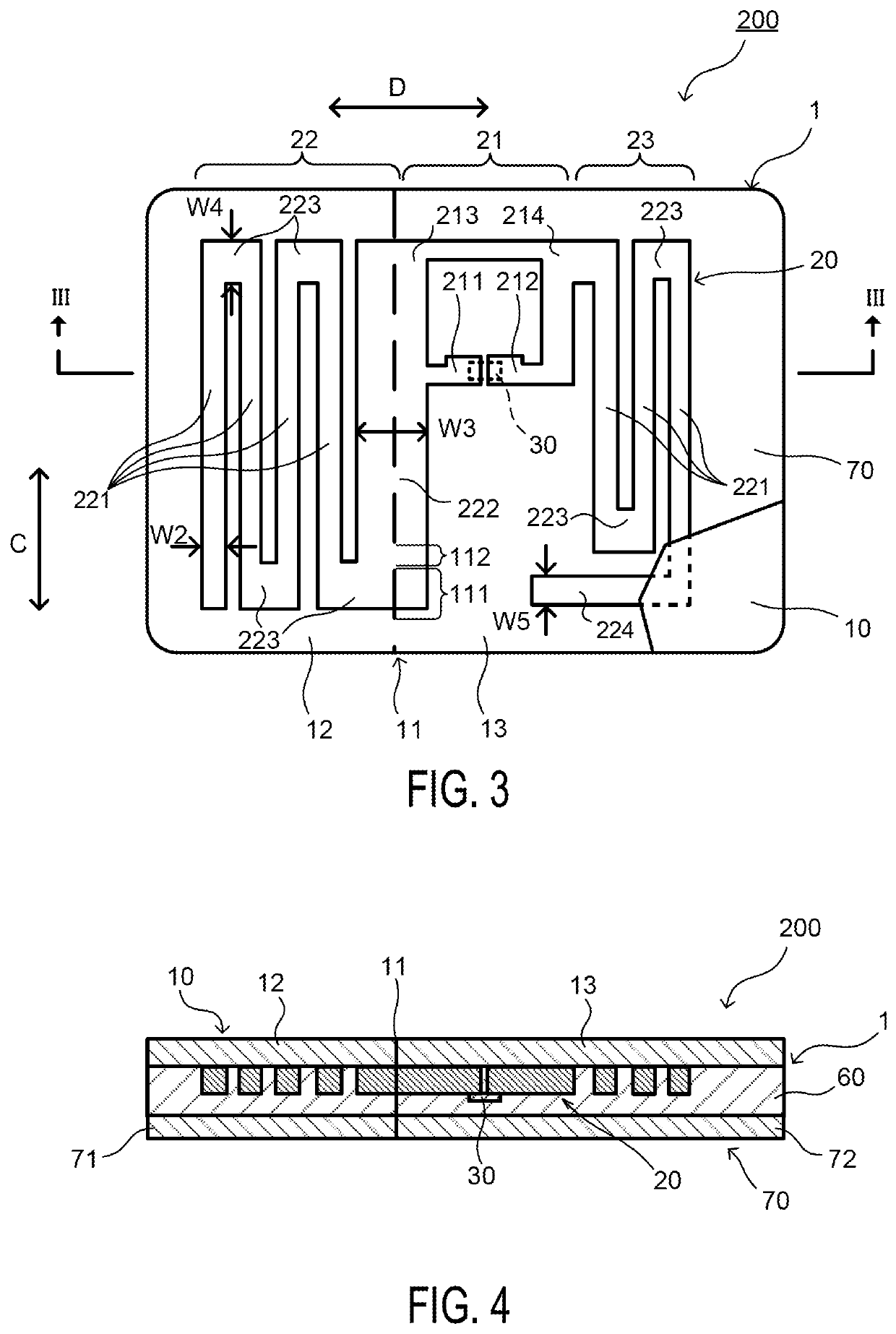
[0060]An RFID tag 200 according to a second embodiment of the present invention will be described. In each of the embodiments shown below, differences from the first embodiment will be mainly described, and components that have similar functions are assigned the same reference numerals and detailed descriptions thereof will be omitted.

[0061]FIG. 3 is a schematic plan view showing the RFID tag 200 according to the second embodiment with a part thereof cut out, and FIG. 4 is a sectional view taken along a line III-III shown in the RFID tag 200 according to the second embodiment of the present invention.

[0062]The RFID tag 200 is provided with the substrate 10 that can be separated into the first substrate portion 12 and the second substrate portion 13 by the tear off line 11, the dipole antenna 20 that is formed of a metal foil so as to have a predetermined antenna length and a predetermined antenna width, the dipole antenna 20 being arranged so as to spread over both sides of the tear...

third embodiment

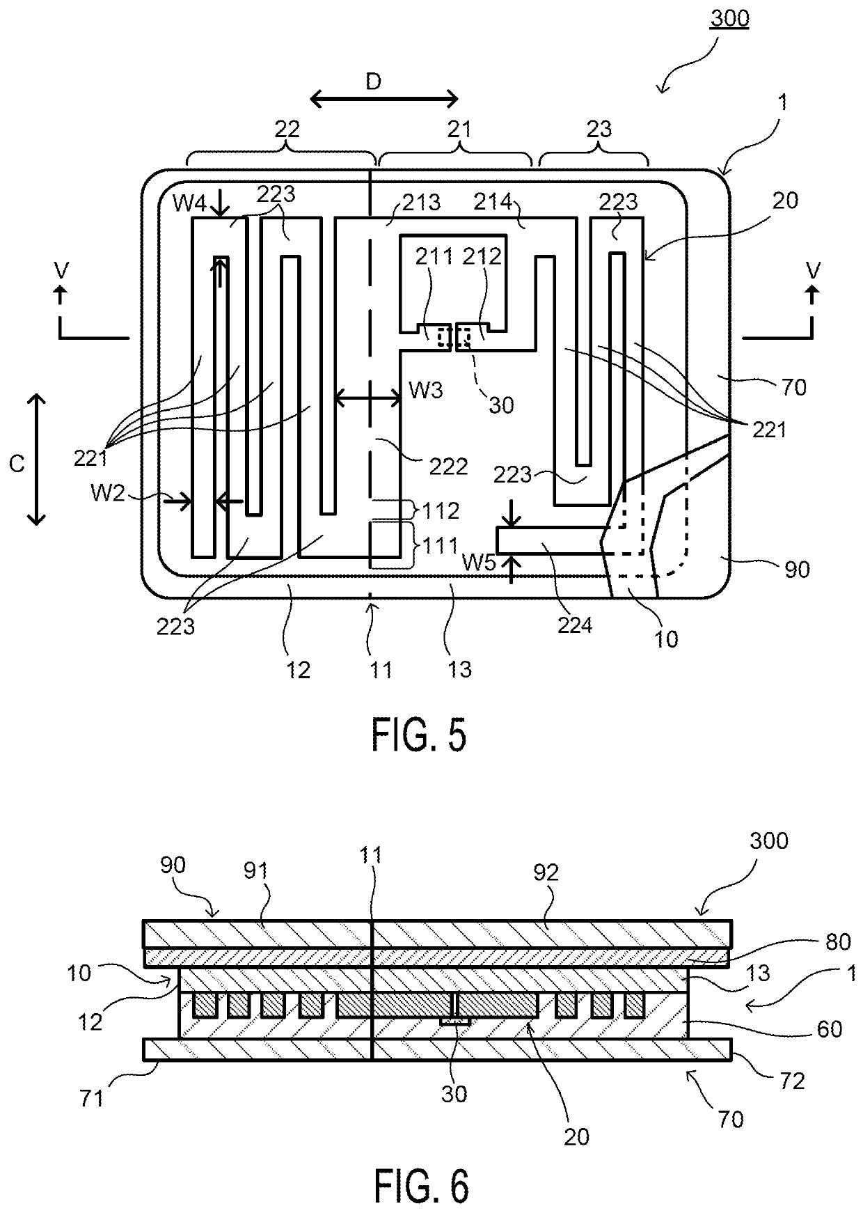
[0072]An RFID tag 300 according to a third embodiment of the present invention will be described. In each of the embodiments shown below, differences between the first embodiment and the second embodiment will be mainly described, and components that have similar functions are assigned the same reference numerals and detailed descriptions thereof will be omitted.

[0073]In the third embodiment, a holding substrate 90 that holds the substrate 10 is overlaid on a surface of the RFID tag 300 (a surface of the substrate 10 on which the dipole antenna 20 is not overlaid).

[0074]FIG. 5 is a schematic plan view showing the RFID tag 300 according to the third embodiment with a part thereof cut out, and FIG. 6 is a sectional view taken along a line V-V shown in the RFID tag 300 according to the third embodiment of the present invention.

[0075]As shown in FIG. 6, in the RFID tag 300, the holding substrate 90 is overlaid on the surface of the substrate 10 via a bonding agent or adhesive agent 80. ...


PUM


Abstract

An RFID label includes: a substrate; a dipole antenna formed of a metal foil so as to have a predetermined antenna length and a predetermined antenna width, the dipole antenna being arranged on a surface of the substrate; an IC chip connected to the dipole antenna; and a separator temporarily adhered to an adhesive agent overlaid on the surface of the substrate on which the dipole antenna is arranged, wherein a tear off line cuts through the substrate and the dipole antenna, in at least a part of the dipole antenna, so as to extend along an antenna length direction and so as to be superimposed with the part of the dipole antenna.

Description

TECHNICAL FIELD[0001]The present invention relates to an RFID label and an RFID tag.BACKGROUND ART[0002]In the field of manufacture, management, logistics, and so forth of products, tags that are attached to the products and labels that are affixed to the products, etc. are used. Information related to the products is printed on the tags and the labels so as to be visually visible. In recent years, a technique utilizing an RFID (Radio Frequency Identification), in which identification information written on an IC chip is transmitted and received via a wireless communication, is becoming more and more common in various fields, and the technique is also becoming more familiar in the above-described fields.[0003]There are RFID media such as the tags, the labels, and so forth into which RFID inlays are integrated. The RFID inlay is formed by overlaying the IC chip with such an RFID specification and a line shaped antenna pattern on a substrate. Information related to a target object to ...

Claims


Application Information

Patent Timeline
IPC IPC(8): G06K19/077G06K19/07H01Q1/22H01Q9/28
CPCG06K19/07786G06K19/0776H01Q9/285H01Q1/2208G06K19/0723H01Q9/42G06K19/077H04B1/59G06K19/07798G09F3/0335
Inventor ESCARO, RODLY
Owner SATO HLDG CORP
Why Eureka
Try Eureka