Correction instruction region display apparatus, correction instruction region display method, and correction instruction region display program

Pending Publication Date: 2022-03-10
FUJIFILM CORP
View PDF0 Cites 0 Cited by
  • Summary
  • Abstract
  • Description
  • Claims
  • Application Information

AI Technical Summary

Benefits of technology

The patent aims to prevent unwanted over-correction in a tomographic image of a three-dimensional image when a region of interest is corrected.

Problems solved by technology

However, in the method described in JP1998-57371A (JP-H10-57371A), a user does not know how the regions of interest are set in the tomographic images that exist between the two tomographic images until the set regions of interest are displayed.

Method used


Image

  • Correction instruction region display apparatus, correction instruction region display method, and correction instruction region display program
  • Correction instruction region display apparatus, correction instruction region display method, and correction instruction region display program
  • Correction instruction region display apparatus, correction instruction region display method, and correction instruction region display program

Examples


Embodiment Construction

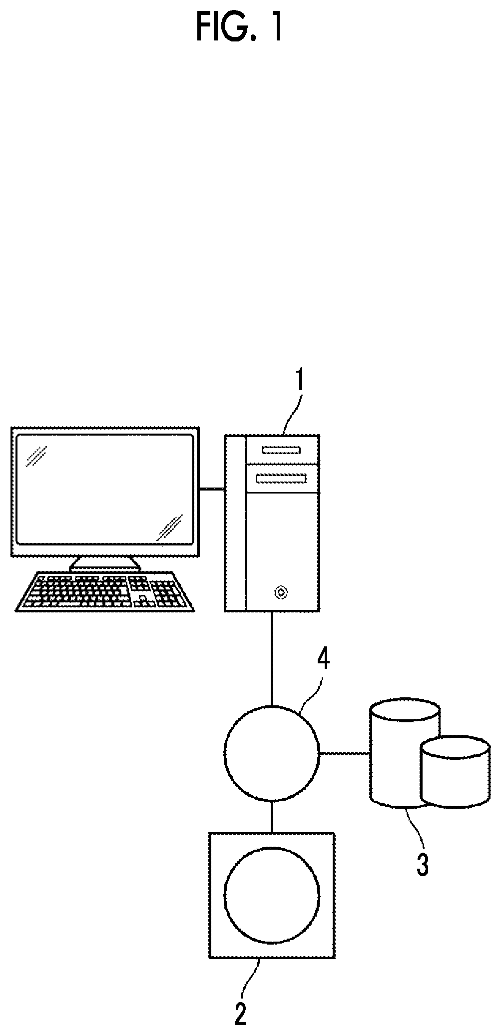
[0029]Hereinafter, an embodiment of the present disclosure will be described with reference to the drawings. FIG. 1 is a hardware configuration diagram showing an outline of a diagnosis support system to which a correction instruction region display apparatus according to the embodiment of the present disclosure is applied. As shown in FIG. 1, in the diagnosis support system, a correction instruction region display apparatus 1, a three-dimensional image capturing apparatus 2, and an image storage server 3 according to the present embodiment are connected to communicate with one another via a network 4.

[0030]The three-dimensional image capturing apparatus 2 is an apparatus that images an area to be diagnosed of a subject and that generates a three-dimensional image representing the area, and specific examples thereof include a CT apparatus, an MRI apparatus, and a positron emission tomography (PET) apparatus. The three-dimensional image generated by the three-dimensional image captur...


PUM


Abstract

A first display control unit displays a first tomographic image of a three-dimensional image consisting of a plurality of tomographic images on a display unit, and superimposes and displays, as a first cross-section correction instruction region, a cross-section of a three-dimensional correction instruction region on the first tomographic image, which is used to correct a boundary of a region of interest extracted from the three-dimensional image, on the first tomographic image. A second display control unit displays at least one second tomographic image adjacent to the first tomographic image, which includes the three-dimensional correction instruction region, on the display unit, and superimposes and displays, as a second cross-section correction instruction region, a cross-section of the three-dimensional correction instruction region on the second tomographic image, on the second tomographic image.

Description

CROSS-REFERENCE TO RELATED APPLICATIONS[0001]This application is a Continuation of PCT International Application No. PCT / JP2020 / 018394 filed on May 1, 2020, which claims priority under 35 U.S.C § 119(a) to Japanese Patent Application No. 2019-104701 filed on Jun. 4, 2019. Each of the above application(s) is hereby expressly incorporated by reference, in its entirety, into the present application.BACKGROUND OF THE INVENTION1. Field of the Invention[0002]The present disclosure relates to a correction instruction region display apparatus, a correction instruction region display method, and a non-transitory computer readable recording medium storing a correction instruction region display program that display a correction instruction region that is used to correct a boundary of a region of interest extracted in a three-dimensional image.2. Description of the Related Art[0003]In recent years, advances in medical equipment, such as a computed tomography (CT) apparatus and a magnetic reson...

Claims


Application Information

Patent Timeline
IPC IPC(8): G06T11/00G06K9/20A61B6/03A61B6/00
CPCG06T11/008G06K9/2054G06T2207/30004A61B6/466A61B6/463A61B6/032G01T1/161A61B5/055G06T7/11G06T2200/24G06T2207/10081G06T2207/10088G06T2207/20081G06T2207/20084G06T2207/20104G06V10/25G06V2201/031G06V10/82G06V10/22
Inventor YUZAWA, TAKUYA
Owner FUJIFILM CORP
Why Eureka
Try Eureka