
Series Tee Splitter for Impedance Measurements

a series tee splitter and impedance measurement technology, applied in the direction of impedence measurement, coupling device connection, instruments, etc., can solve the problems of high cost, inability to measure device transfer functions, and instrumentation that cannot measure high impedance in the hz and khz range needed for power system device characterization, and the option does not incorporate fixtures needed to measure large test objects with high impedances

Active Publication Date: 2022-03-31
NAT TECH & ENG SOLUTIONS OF SANDIA LLC
View PDF5 Cites 2 Cited by
  • Summary
  • Abstract
  • Description
  • Claims
  • Application Information

AI Technical Summary

Benefits of technology

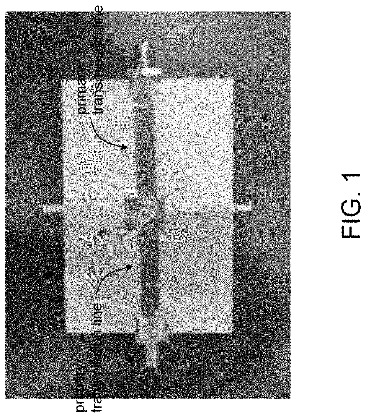
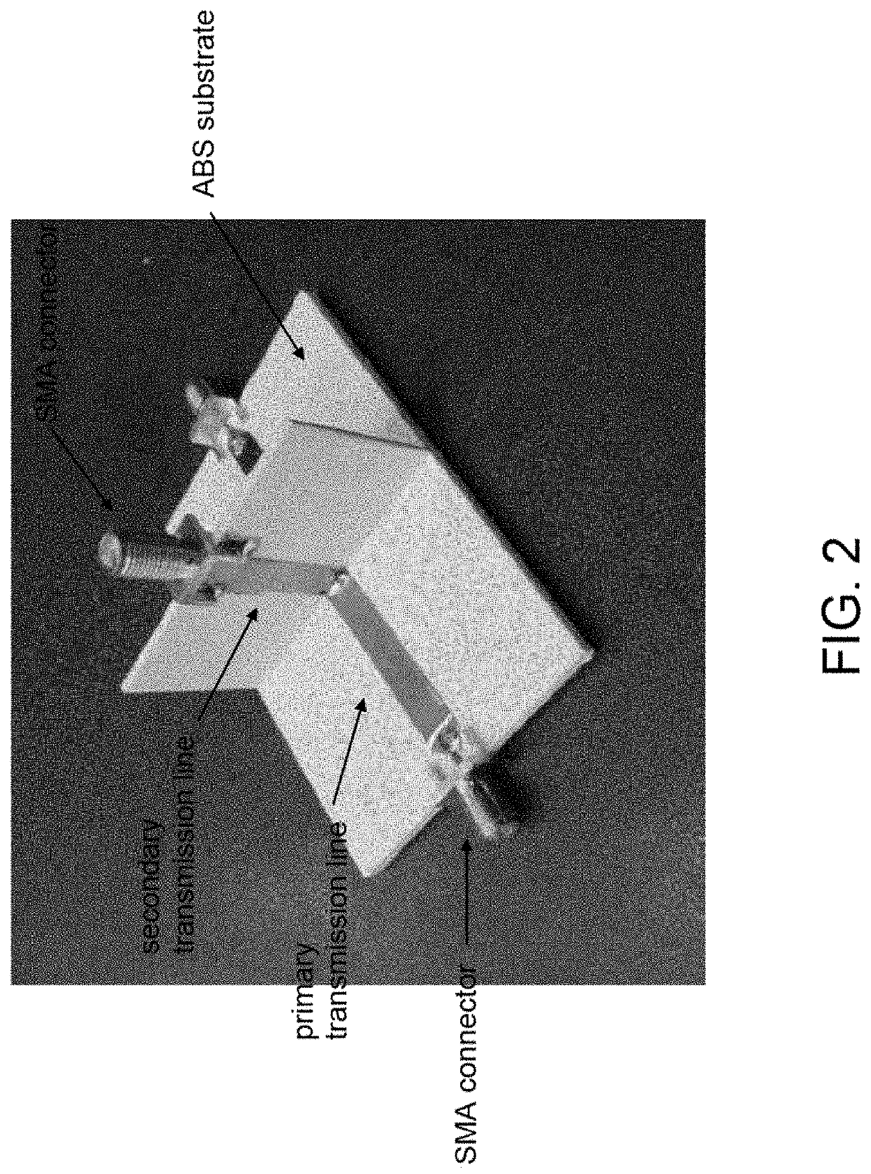
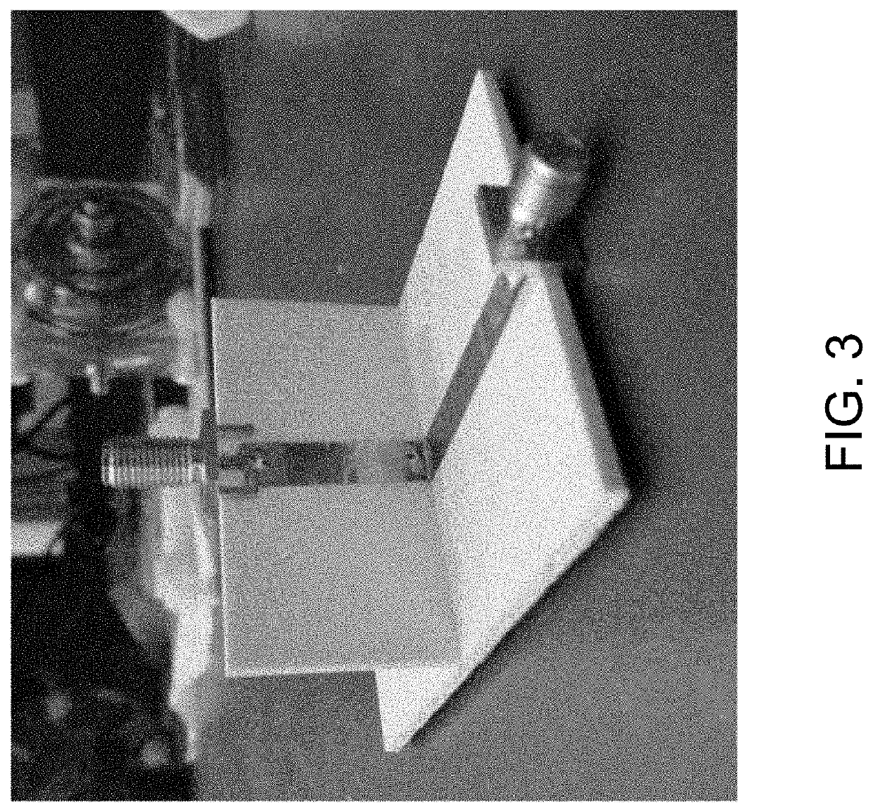
The present invention is a device called a series tee splitter, which is used to measure the impedance of a load. It consists of a primary electromagnetic transmission line and a secondary electromagnetic transmission line placed in a series path with the primary line. The secondary line is attached to a network analyzer to measure the load impedance. The primary line can be a microstrip line structure and the secondary line can be a parallel conductor structure built on a T-shaped substrate with the secondary line on the stem of the T-shaped substrate. The technical effect of this invention is to provide a reliable and accurate way to measure the impedance of a load, which can be useful in various fields such as electronics, telecommunications, and sensors.

Problems solved by technology

While this instrument can measure high impedances, it has the disadvantages of high cost and the inability to measure device transfer functions.
In general, this instrument does not have the capability to measure high impedances in the Hz and kHz ranges needed for power system device characterization.
An impedance analysis option is available with this instrument with dedicated connections (gain-phase test port), however, this option does not incorporate fixtures needed to measure large test objects with high impedances.
Transmission line stubs are commonly mentioned in impedance matching texts; however, practical implementation is not widely provided for series stubs.

Method used


Image

  • Series Tee Splitter for Impedance Measurements
  • Series Tee Splitter for Impedance Measurements
  • Series Tee Splitter for Impedance Measurements

Examples


Embodiment Construction

[0022]An approach to finding the impedance of a test object is to measure the scattering parameters with a VNA and perform a matrix transformation to calculate the impedance. A common approach is to use a 1-port reflection coefficient measurement to extract impedance in an intermediate impedance range, where the governing equation to calculate the impedance is given in equation (1),

ZL=Z0⁢1+S1⁢11-S1⁢1(1)

where ZL is the load impedance, Z0 is the VNA port reference impedance, and S11 is the measured reflection coefficient from the device under test. A limitation of the 1-port measurement is the maximum measurable impedance is governed by the resolution with which the network can measure the magnitude of S11, which can have a dynamic range of a few hundred dB and a precision of a few tenths of dB. Measurements on a Keysight E5061B VNA have shown a maximum sensitivity around 100 kΩ with typical measurement settings for this measurement approach.

[0023]A 2-port measurement approach can be ...


PUM


Abstract

A series tee splitter comprises a primary electromagnetic transmission line and a secondary electromagnetic transmission line that is placed in a series path with the primary electromagnetic transmission line, wherein a load is attached to the end of the secondary electromagnetic transmission line and a network analyzer is connected to opposite ends of the primary electromagnetic transmission line to measure a load impedance. This configuration increases the high impedance measurement limit of the network analyzer normally seen for reflection measurements. The series tee splitter can be electrically small to provide broadband impedance information.

Description

CROSS-REFERENCE TO RELATED APPLICATION[0001]This application claims the benefit of U.S. Provisional Application No. 63 / 084,721, filed Sep. 29, 2020, which is incorporated herein by reference.STATEMENT OF GOVERNMENT INTEREST[0002]This invention was made with Government support under Contract No. DE-NA0003525 awarded by the United States Department of Energy / National Nuclear Security Administration. The Government has certain rights in the invention.FIELD OF THE INVENTION[0003]The present invention relates to electrical impedance measurements and, in particular, to a series tee splitter for impedance measurements.BACKGROUND OF THE INVENTION[0004]Broadband impedance measurements can be used to develop circuit models and behavioral models for power system components to determine how they respond to a high-altitude electromagnetic pulse (HEMP) event from the early-time to the late-time portions of the event. During component susceptibility testing, device transient response measurements ...

Claims


Application Information

Patent Timeline
Patent Type & Authority Applications(United States)
IPC IPC(8): G01R27/16H01R9/05
CPCG01R27/16H01R2201/20H01R9/05H01R24/547G01R27/04G01R27/32G01R27/025
Inventor HALLIGAN, MATTHEWBOWMAN, TYLER
Owner NAT TECH & ENG SOLUTIONS OF SANDIA LLC
Learn More