Functional test equipment including relay system and test method using the functional test equipment

a functional test and relay technology, applied in the direction of electronic circuit testing, measurement devices, instruments, etc., can solve the problems of affecting the overall lifetime performance of the part, affecting the reliability of the test equipment, etc., to achieve stable power supply

Active Publication Date: 2022-03-31
NAN YA TECH
View PDF3 Cites 1 Cited by
  • Summary
  • Abstract
  • Description
  • Claims
  • Application Information

AI Technical Summary

Benefits of technology

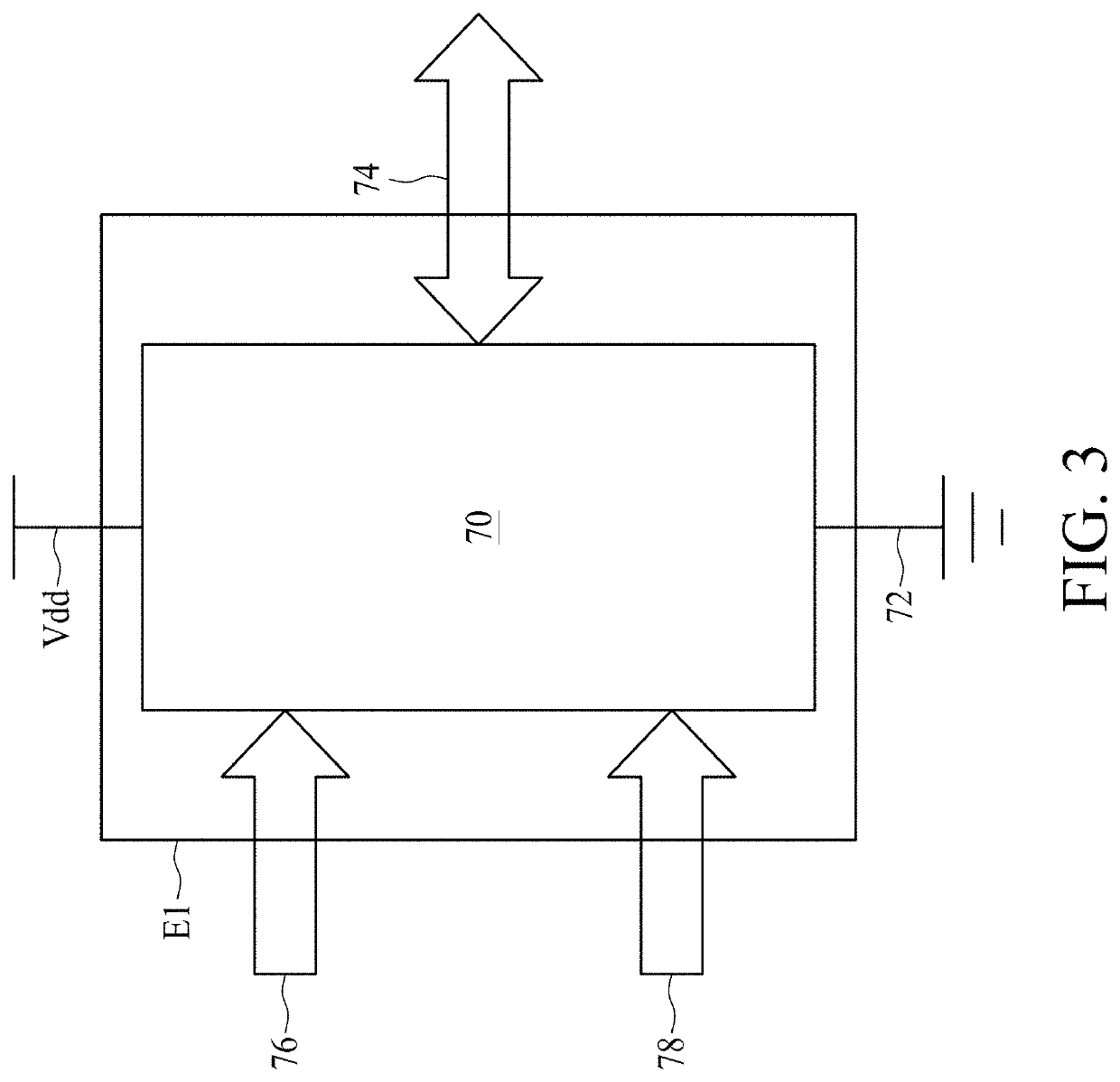
[0024]The testing of devices is of great importance. Conventional automatic testing equipment (ATE) cannot accurately reflect voltage variation in the power supply input to the device under test because the ATE generally provides a relatively stable power supply compared to the power supply provided to the devices installed in electronics such as computers or mobile phones. Therefore, conventional ATE is unable to screen out problematic devices under test at the stage of verification. The present disclosure provides a functional test equipment including a relay system and a pair of power supplies. In addition, the pair of power supplies provides a pair of different supply voltages to a device under test (DUT) placed in the functional test equipment. The combination of the relay system and the pair of power supplies provides a test to the DUT to simulate situations a memory chip may encounter in actual use. Moreover, artificial drops of power supplied to the DUT are made to verify the robustness of the DUT. Therefore, a more realistic simulation when the DUT is being tested can be realized according to the present disclosure.

Problems solved by technology

Many memory testers run continuously, and testing time is considered a major factor in the cost of the finished product.
Another issue specific to testing non-volatile memories is that repeated writes to cells of a memory can degrade the overall lifetime performance of the part.
Conventional automatic testing equipment (ATE) cannot accurately reflect voltage variation in the power supply input to the device under test because the ATE generally provides a relatively stable power supply compared to the power supply provided to the devices installed in electronics such as computers or mobile phones.
Therefore, conventional ATE is unable to screen out problematic devices under test at the stage of verification.

Method used


Image

  • Functional test equipment including relay system and test method using the functional test equipment
  • Functional test equipment including relay system and test method using the functional test equipment
  • Functional test equipment including relay system and test method using the functional test equipment

Examples


Embodiment Construction

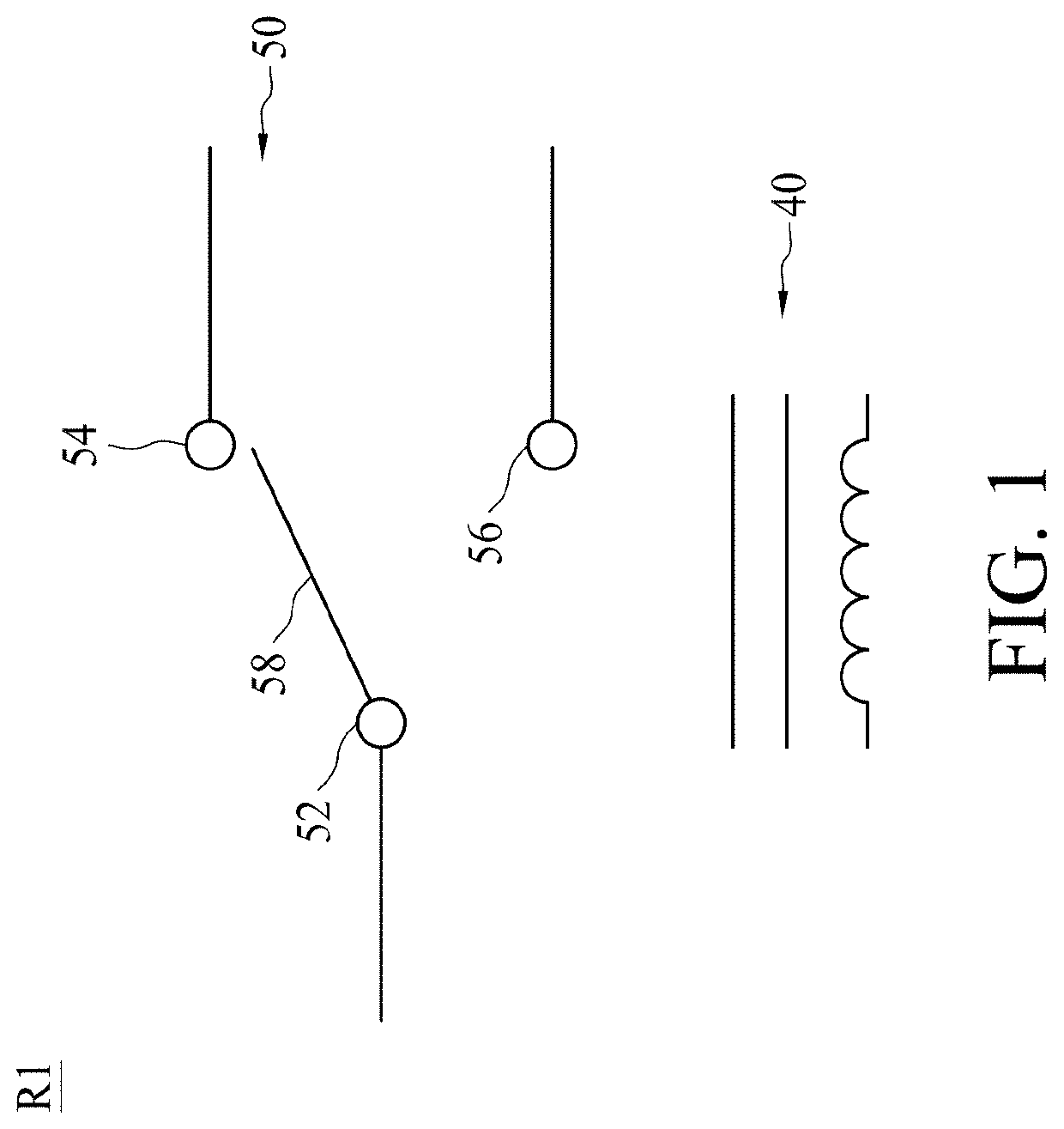
[0036]Embodiments, or examples, of the disclosure illustrated in the drawings are now described using specific language. It shall be understood that no limitation of the scope of the disclosure is hereby intended. Any alteration or modification of the described embodiments, and any further applications of principles described in this document, are to be considered as normally occurring to one of ordinary skill in the art to which the disclosure relates. Reference numerals may be repeated throughout the embodiments, but this does not necessarily mean that feature(s) of some embodiments apply to another embodiment, even if they share the same reference numeral.

[0037]It shall be understood that, although the terms first, second, third, etc. may be used herein to describe various elements, components, regions, layers or sections, these elements, components, regions, layers or sections are not limited by these terms. Rather, these terms are merely used to distinguish one element, compone...


PUM


Abstract

The present disclosure provides functional test equipment for a device under test and method of testing the device under test. The functional test equipment includes a first power supply, a second power supply and a relay system. The first power supply is configured to generate a first supply voltage. The second power supply is configured to generate a second supply voltage different from the first supply voltage. The relay system is configured to electrically couple the first power supply or the second power supply to the device under test, wherein the first supply voltage is applied to the device under test for a first duration and the second supply voltage is applied to the device under test for a second duration less than the first duration.

Description

TECHNICAL FIELD[0001]The present disclosure relates to a functional test equipment and a method of testing a device under test using the functional test equipment, more particularly, to a functional test equipment including a relay system and a test method using the functional test equipment.DISCUSSION OF THE BACKGROUND[0002]Electronic devices have become extremely common in daily life. Along with personal computers in the home, many individuals carry more than one productivity tool for various and sundry purposes. Most personal productivity electronic devices include some form of non-volatile memory. Cell phones utilize non-volatile memory in order to store and retain user-programmed phone numbers and configurations when the power is turned off.[0003]As non-volatile memories become larger, denser and more complex, testers must be able to handle the increased size and complexity without significantly increasing the time it takes to test them. Many memory testers run continuously, an...

Claims


Application Information

Patent Timeline
Patent Type & Authority Applications(United States)
IPC IPC(8): G01R31/28G01R31/327
CPCG01R31/2879G01R31/2834G01R31/3278
Inventor YANG, WU-DER
Owner NAN YA TECH
Why Eureka
Try Eureka