
Power generating system for a rotatory dental apparatus

Pending Publication Date: 2022-04-07
AEROBINE INC
View PDF0 Cites 0 Cited by
  • Summary
  • Abstract
  • Description
  • Claims
  • Application Information

AI Technical Summary

Benefits of technology

The technical effects of this patent are that the power generating system has a long life and is economical to manufacture.

Problems solved by technology

The high temperatures of autoclaving decrease the life of the generator.

Method used


Image

  • Power generating system for a rotatory dental apparatus
  • Power generating system for a rotatory dental apparatus
  • Power generating system for a rotatory dental apparatus

Examples


Embodiment Construction

[0023]Subject matter will now be described more fully hereinafter. Subject matter may, however, be embodied in a variety of different forms and, therefore, covered or claimed subject matter is intended to be construed as not being limited to any exemplary embodiments set forth herein; exemplary embodiments are provided merely to be illustrative. Likewise, a reasonably broad scope for claimed or covered subject matter is intended. Among other things, for example, the subject matter may be embodied as assembly and methods of use thereof. The following detailed description is, therefore, not intended to be taken in a limiting sense.

[0024]The word “exemplary” is used herein to mean “serving as an example, instance, or illustration.” Any embodiment described herein as “exemplary” is not necessarily to be construed as preferred or advantageous over other embodiments. Likewise, the term “embodiments of the present invention” does not require that all embodiments of the invention include th...


PUM


Abstract

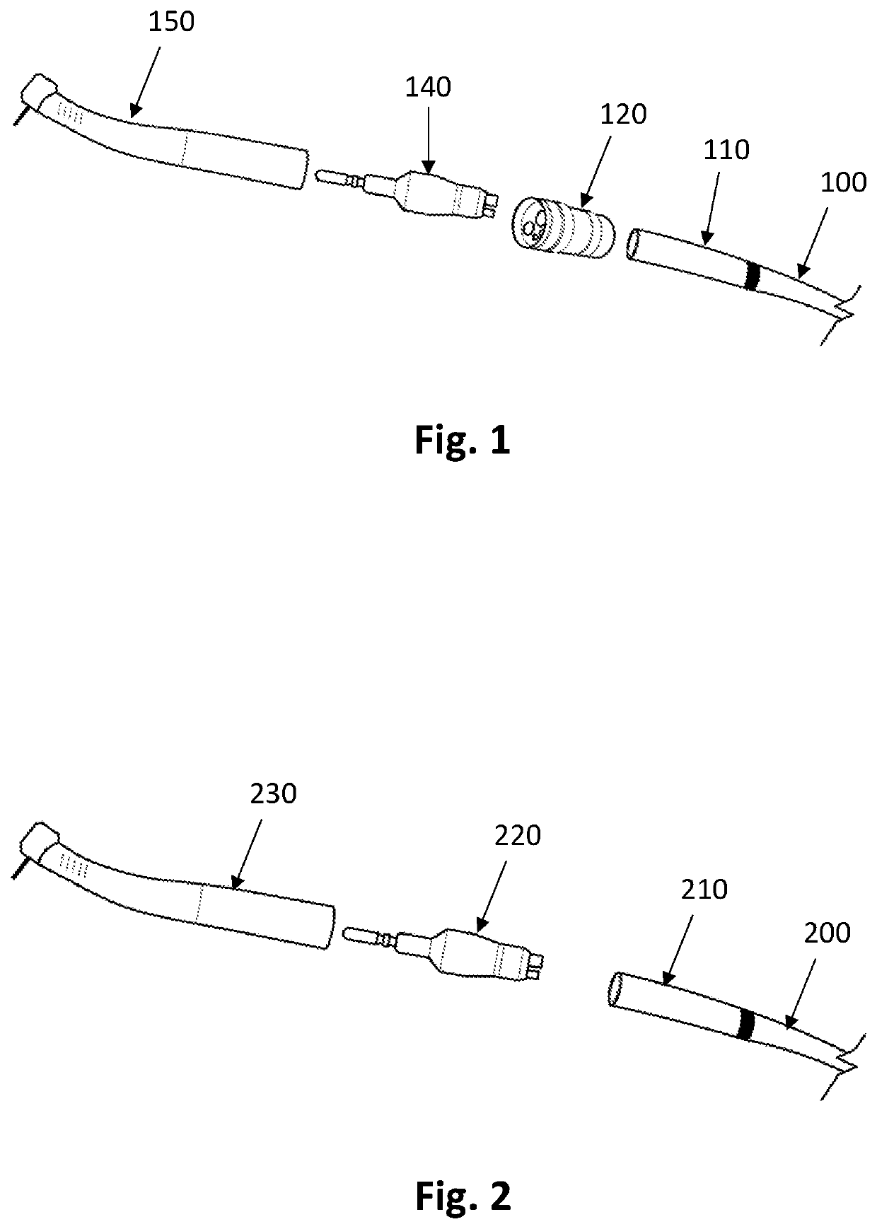
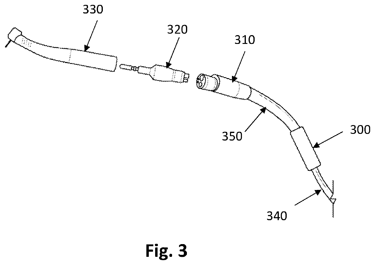
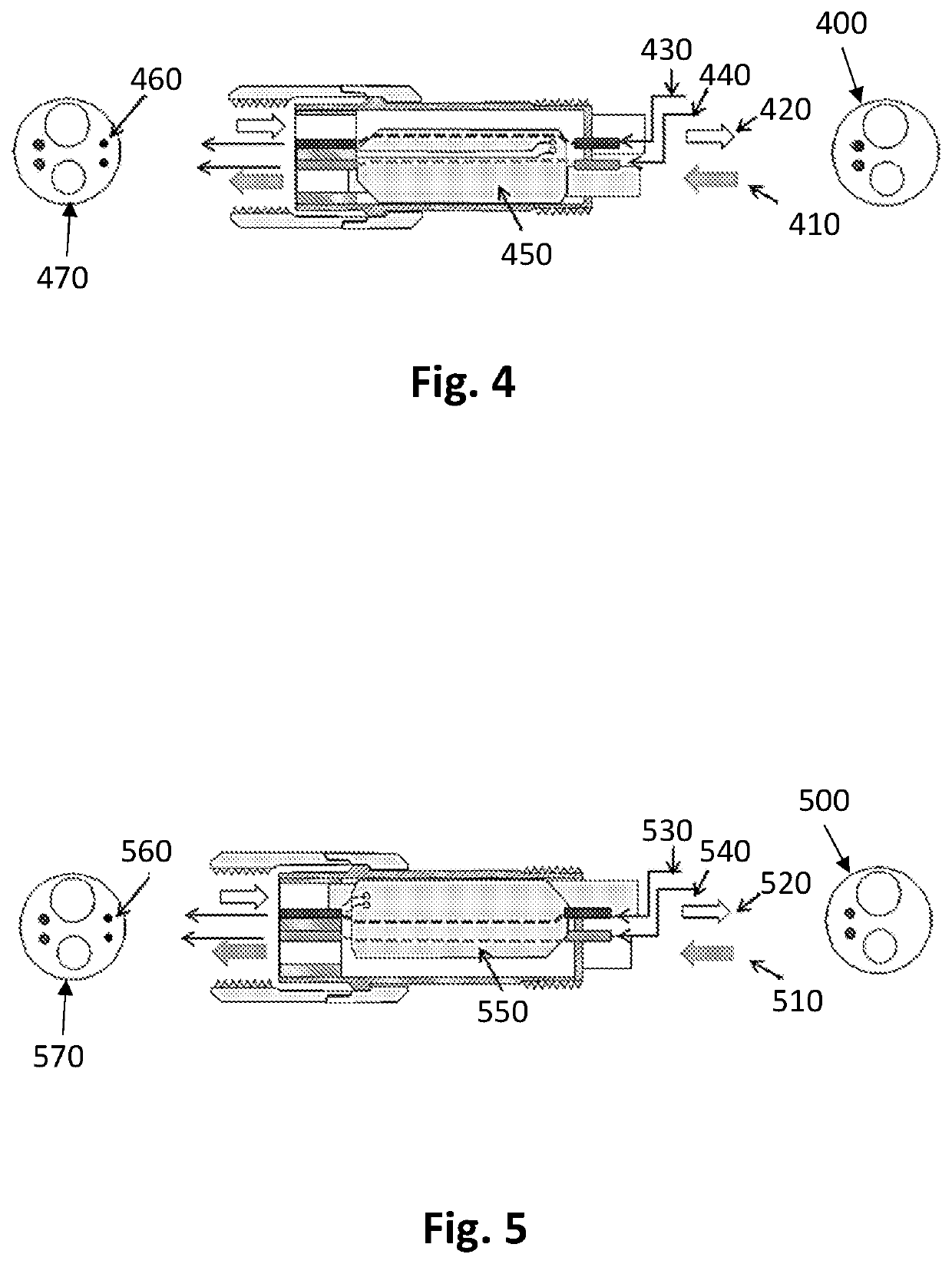
Disclosed is a power generating system for a rotatory dental apparatus that can power the illumination source. The rotatory dental apparatus includes a supply hose having a hose connector at its one end. A swivel coupling connects the hose connector to the dental handpiece. The power generating system can be configured in the hose supply. In one case, the power generating system can be installed in the hose connector of the hose supply. In one case, the power generating system can be interposed between the two sections of the hose supply. In one case, the power generating system can be installed in a hose coupling that is interposed between the swivel coupling and the hose connector.

Description

CROSS-REFERENCE TO RELATED APPLICATIONS[0001]This application claims priority to the U.S. provisional patent application Ser. No. 17 / 111,178 filed on Dec. 3, 2020, which claims priority of 63 / 092,975, filed on Oct. 16, 2020 which is incorporated herein by reference in its entirety.FIELD OF INVENTION[0002]The present invention is directed to a power generating system, and more particularly, the present invention relates to a power generating system for a dental hose that powers an illumination source downstream of the power generating system.BACKGROUND[0003]In modern dentistry, a lighting system is often integrated with a rotatory dental tool, hereafter called dental handpiece, so that dentists can see the working area illuminated inside a patient's mouth from a light source attached to the handpiece. The conventional way of delivering power to such light source involves electrical power supply and controller, electrical wires inside the air / water servicing hose, and fiber optic bund...

Claims


Application Information

Patent Timeline
IPC IPC(8): A61C1/05A61C1/00H02K7/18F01K15/00
CPCA61C1/05A61C1/0061F01K15/00H02K7/1823A61C1/052A61C1/0038A61C1/08A61C1/088
Inventor KIM, YONG WEONHSIEH, CHINPAO
Owner AEROBINE INC
Features
  • Generate Ideas
  • Intellectual Property
  • Life Sciences
  • Materials
  • Tech Scout
  • Unparalleled Data Quality
  • Higher Quality Content
  • 60% Fewer Hallucinations
Learn More