Apparatus and method for monitoring differential pressure

a differential pressure and apparatus technology, applied in the field of pressure monitoring devices, can solve the problems of knowingly being used on patients, high repair costs, and inability to effectively sterilize or high-level disinfection of leaking endoscopes,

Pending Publication Date: 2022-04-21
ANTONIOLI HILARY C
View PDF0 Cites 0 Cited by
  • Summary
  • Abstract
  • Description
  • Claims
  • Application Information

AI Technical Summary

Benefits of technology

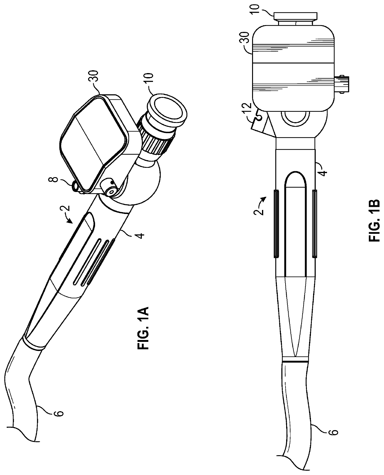
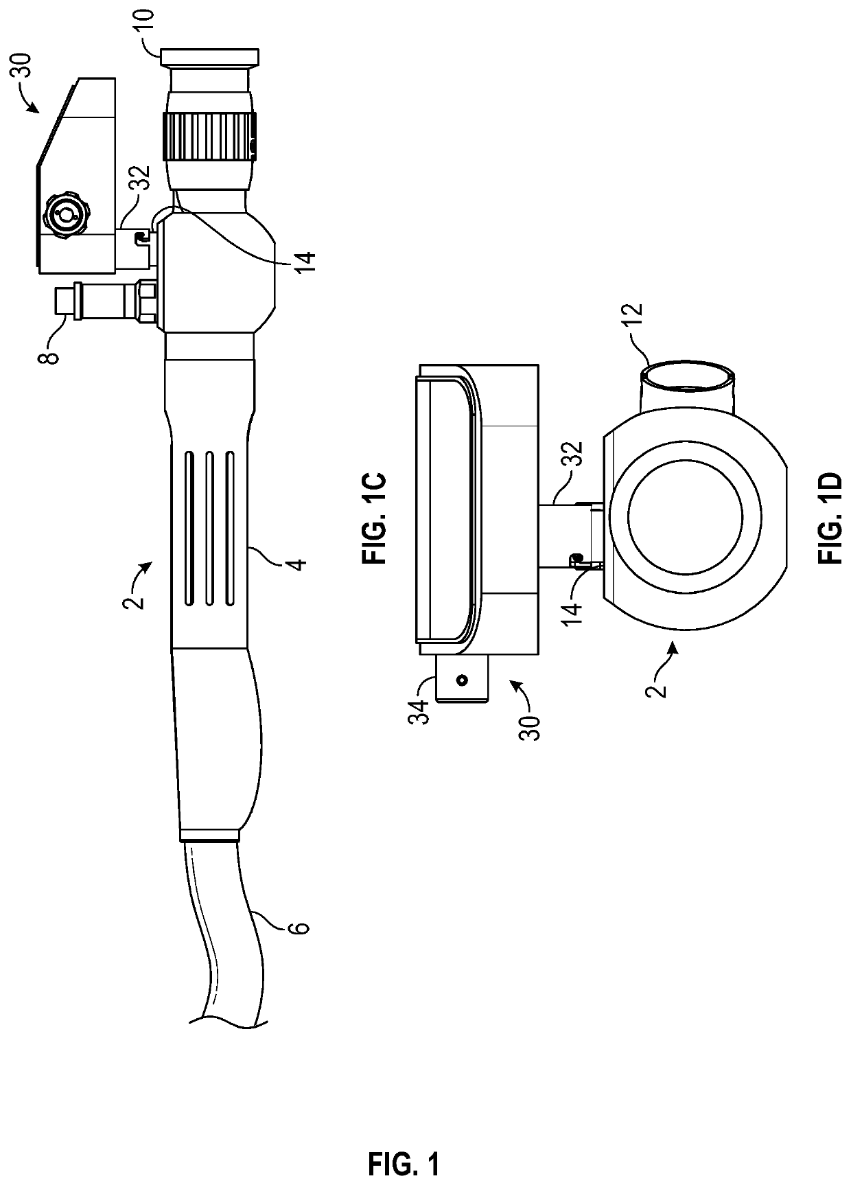
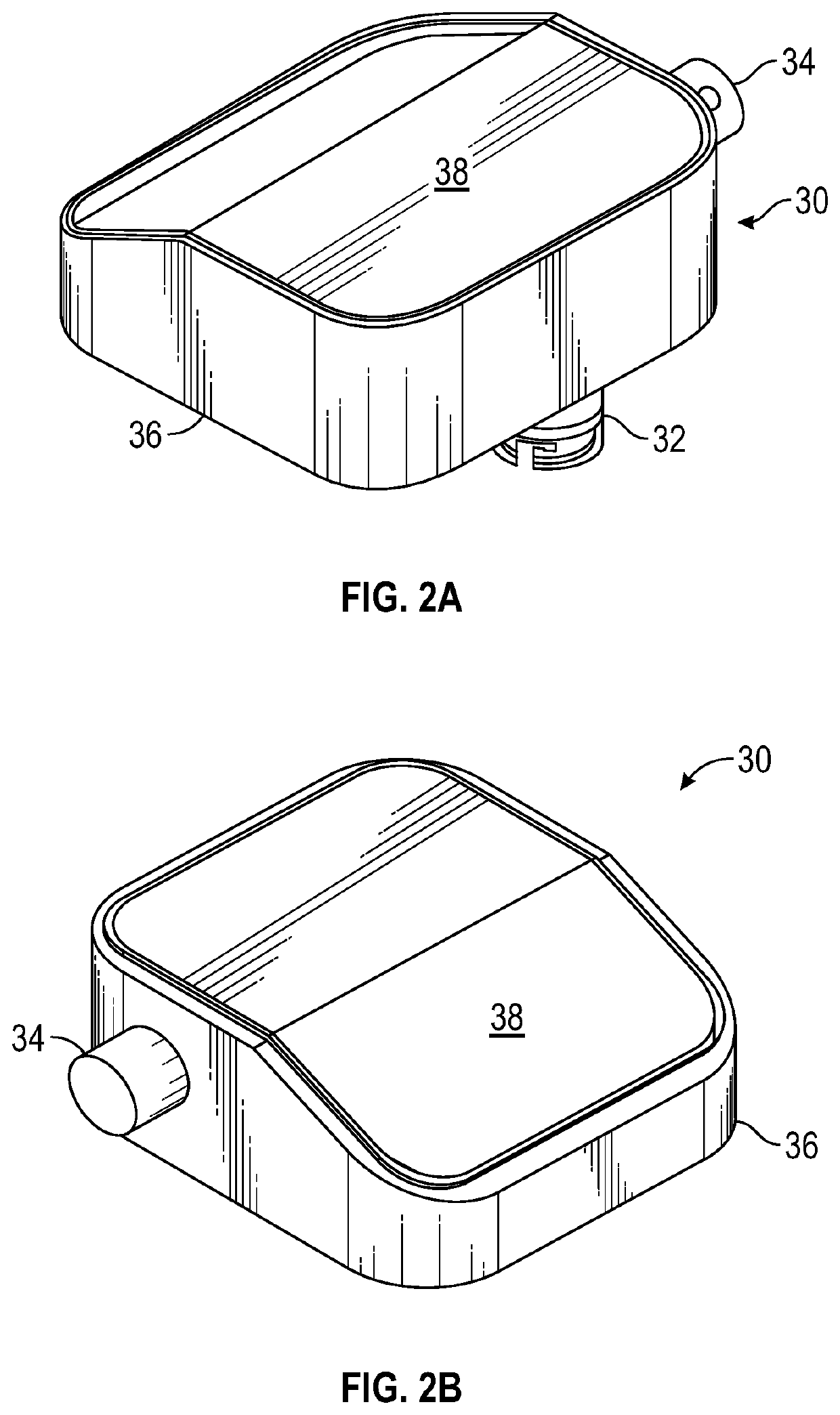
[0006]In accordance with the teachings of the present disclosure, a pressure monitoring control module is provided for use with a tool such as a medical endoscope. In a first embodiment, the control module includes a housing that is fluidically and releasably coupled with an internal volume of the endoscope. A pump is used to change the pressure inside the device housing and endoscope, thereby establishing a pressure differential from the ambient environment. During an endoscopy procedure, the pressure inside the device housing is monitored, and a

Problems solved by technology

By definition, a leaking endoscope cannot be effectively sterilized or high-level disinfected, and would never knowingly be used on a patient.
However, if cleaning and sterilization is undertaken with a leak present, the interior of the endoscope can b

Method used


Image

  • Apparatus and method for monitoring differential pressure
  • Apparatus and method for monitoring differential pressure
  • Apparatus and method for monitoring differential pressure

Examples


first embodiment

[0056]The second version of the control module 30 according to the invention is an active embodiment and is shown in FIGS. 4A, 4B and 5. The active device functions identically to the passive device with one exception; an internal piston assembly is added to the active device, thus eliminating the need to connect to an external pumping device as discussed above for the passive device. The addition of the piston assembly in the active device enables the control module 30 to modify the internal pressure to a level different enough to allow sensing of a leak anywhere within the monitored cavities.

[0057]The active version of the control module 30 has a pump in the form of a piston assembly 50 that includes a piston 52, a compression spring 54, a check valve 56 and a piston cavity 58. The piston assembly 50 is shown in exploded form in FIG. 5. The control module 30 also has a drive assembly 60 that includes a cam 62, a planetary DC motor 64 and a motor mount 66. The motor 64 rotates an a...

second embodiment

[0069]the pressure monitoring control module according to the invention is shown in FIGS. 8-10B. Referring to FIGS. 8 and 9, a pressure monitoring control module 120 is located remotely from a tool 2 (endoscope) and is releasably connected to the endoscope by a disposable or reusable hose 122 with a filter. The control module 120 includes a housing 124 having a front wall configured as a control panel 126. One end of the hose 122 is connected to an outlet port 128 provided at the lower left in the control panel 126 and an opposite end of the hose is connected to a pressure port 14 of the endoscope 2. The differential pressure created by the control module 120 is communicated to the endoscope 2 via the hose 122. The hose 122 can be very small in diameter, as volume flow rate through the hose is not an important factor.

[0070]The control panel 126 of the control module 120 is shown in more detail in FIG. 9. An ON / OFF push button power switch 130 provided at the upper left in the contro...


PUM


Abstract

A pressure monitoring device used to monitor for leaks in a tool such as a medical endoscope. The device includes a housing having an internal volume fluidically coupled with an internal volume of the tool to form a combined internal volume. A pump changes the pressure inside the combined internal volume thereby establishing a baseline pressure at a pressure differential from the ambient environment. During operation of the tool, the pressure inside the combined internal volume is monitored for a change exceeding a predefined limit and such a change results in the device issuing an alarm signal indicating a leak has occurred in the tool. The device housing can be directly mounted to the tool, located remotely and connected with a coupling hose, or integrated with an accessory device connected to the tool. Preferably, the pressure differential is negative relative to ambient when the tool is a medical endoscope.

Description

CROSS-REFERENCE TO RELATED APPLICATIONS[0001]This application is a continuation-in-part of the co-pending U.S. patent application Ser. No. 15 / 924,505 filed Mar. 19, 2018 and claims the benefit of the priority date of U.S. Provisional Patent Application Ser. No. 62 / 474,648, titled APPARATUS AND METHOD FOR MONITORING DIFFERENTIAL PRESSURE, filed Mar. 22, 2017.FIELD OF THE INVENTION[0002]This present disclosure relates generally to a pressure monitoring device coupled to a closed-cavity tool and, more particularly, to an apparatus and a method for monitoring pressure to detect a leakage-type failure of a medical device such as an endoscope by creating and monitoring a differential pressure to the external atmospheric pressure.BACKGROUND OF THE INVENTION[0003]An endoscope is an illuminated optical, typically slender and tubular instrument used to look deep into the body and used in a procedure called an endoscopy. Different types of endoscopes have been developed to be used in different...

Claims


Application Information

Patent Timeline
IPC IPC(8): A61B1/00G01M3/32
CPCA61B1/00142A61B1/00055A61B2090/0809G01M3/3263A61B1/00057A61B2090/064A61B1/00006
Inventor ANTONIOLI, HILARY C.
Owner ANTONIOLI HILARY C
Why Eureka
Try Eureka