Flow body for an aircraft having a solid trailing-edge component

a technology of flow body and trailing edge component, which is applied in the direction of de-icing equipment, spars/stringers, weight reduction, etc., can solve the problems of limiting the available size of an effective area and higher manufacturing costs, and achieve the effect of higher manufacturing costs

Pending Publication Date: 2022-04-21
AIRBUS OPERATIONS GMBH
View PDF4 Cites 0 Cited by
  • Summary
  • Abstract
  • Description
  • Claims
  • Application Information

AI Technical Summary

Benefits of technology

[0005]The use of a honeycomb part at the trailing edge of a flow body limits the available size for an effective area that is anti- or de-iced. Furthermore, the honeycomb / sandwich design leads to higher manufacturing costs.

Problems solved by technology

The use of a honeycomb part at the trailing edge of a flow body limits the available size for an effective area that is anti- or de-iced.
Furthermore, the honeycomb / sandwich design leads to higher manufacturing costs.

Method used


Image

  • Flow body for an aircraft having a solid trailing-edge component
  • Flow body for an aircraft having a solid trailing-edge component

Examples


Embodiment Construction

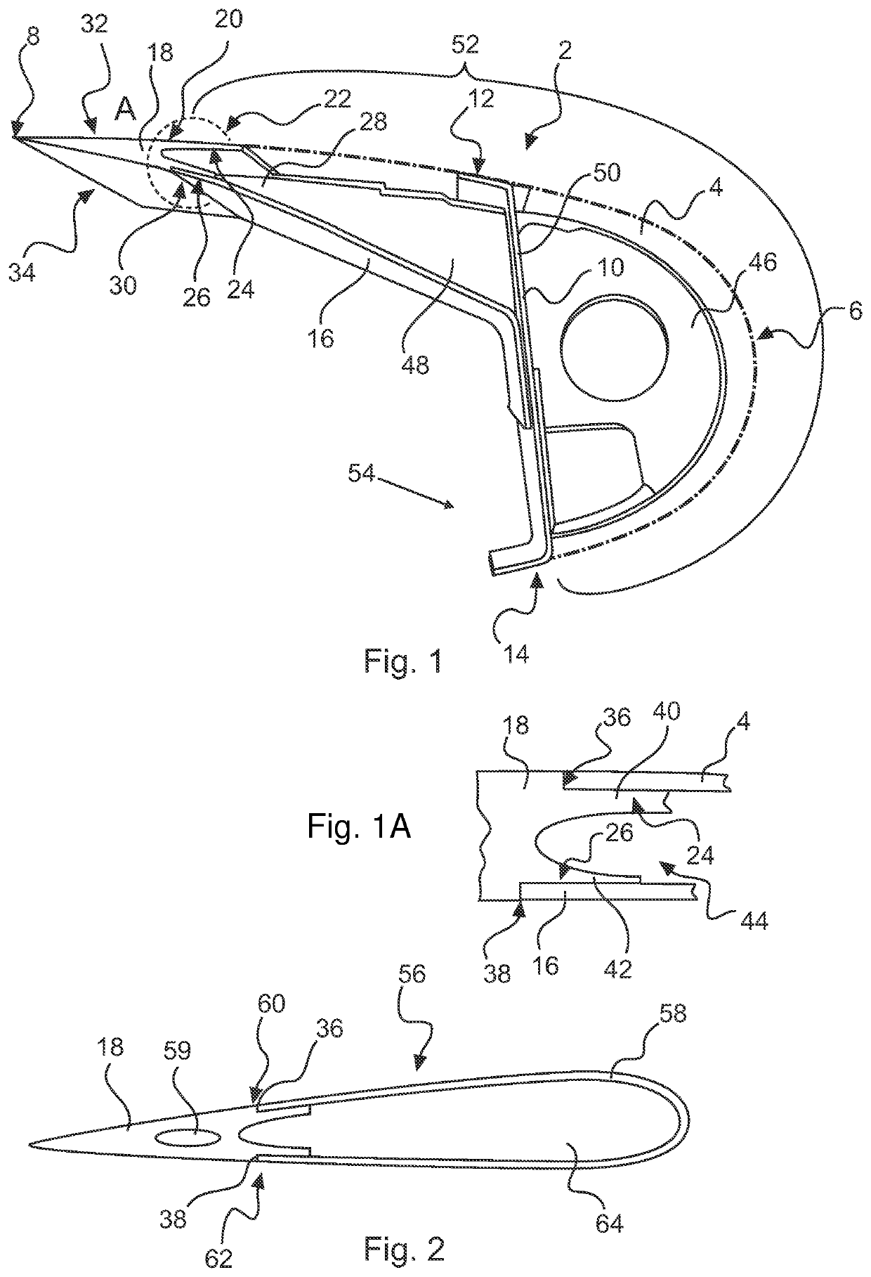
[0041]FIG. 1 shows a sectional view of a flow body 2 for an aircraft, which is exemplarily realized in the form of a leading-edge slat. The flow body 2 comprises a curved front skin 4 having a leading edge 6 in at least one flow condition. The front skin 4 is curved to form an aerodynamic surface with a predetermined flow characteristic. Opposite to the leading edge 6, a trailing edge 8 is positioned. Exemplarily, a spar 10 extends between a top section 12 and a bottom section 14 of the flow body 2, on which the front skin 4 rests. At a side facing away from the leading edge 6, a back skin 16 is arranged, which is attached to a rear side of the spar 10 and extends towards the trailing edge 8.

[0042]The flow body 2 comprises a trailing-edge component 18, which comprises the trailing edge 8. It is an extruded or machined and solid component. For example, the trailing-edge component 18 is made from aluminum in an extrusion process.

[0043]The front skin 4 comprises a first spanwise edge 2...


PUM


Abstract

A flow body for an aircraft, in particular for a wing leading edge device, is proposed, the flow body having a curved front skin having a leading edge and at least one trailing-edge component coupled with at least one spanwise edge of the front skin, wherein the trailing-edge component comprises a constant cross-sectional profile that tapers in a chordwise direction to form two spanwise flow surfaces that end in a trailing edge, and wherein the trailing-edge component is designed for providing a flush transition between the front skin and at least one of the two spanwise flow surfaces.

Description

CROSS-REFERENCES TO RELATED APPLICATIONS[0001]This application claims the benefit of the International Application No. PCT / EP2020 / 064448, filed on May 25, 2020, and of the German patent application No. 10 2019 114 098.6 filed on May 27, 2019, the entire disclosures of which are incorporated herein by way of reference.FIELD OF THE INVENTION[0002]The invention relates to a flow body for an aircraft, in particular for a wing leading edge device, a wing having a fixed wing body and a wing leading-edge device having a flow body and an aircraft having such a wing or at least one such flow body.BACKGROUND OF THE INVENTION[0003]Commercial aircraft often comprise fixed and movable aerodynamic structures with an at least partially hollow structure. Depending on the size and shape of the structures, as well as their optional movability, different design and construction principles are applied. For example, various high lift systems are known, which are based on movable flow bodies for selectiv...

Claims


Application Information

Patent Timeline
Patent Type & Authority Applications(United States)
IPC IPC(8): B64C3/28B64C9/24B64D15/04B64C3/18
CPCB64C3/28B64C3/185B64D15/04B64C9/24B64C2003/146Y02T50/40
Inventor ERBAN, MARCUS
Owner AIRBUS OPERATIONS GMBH
Why Eureka
Try Eureka