

Imaging Optical System, Imaging Apparatus And Focal-Depth Extension Optical System
a technology of imaging apparatus and optical system, which is applied in the field of imaging optical system, imaging apparatus and focal depth extension system, can solve the problems of insufficient extension of focal depth, scattered stray light noise in image capture under circumstances with bright optical sources, etc., and achieve the effect of large focal depth and uniform image quality
- Summary
- Abstract
- Description
- Claims
- Application Information
AI Technical Summary
Benefits of technology
Problems solved by technology
Method used
Image

Examples
first embodiment
[0024]Hereinafter, embodiments of the present invention will be described with reference to the accompanying drawings. Each embodiment described below is only one example for achieving the present invention, and does not limit the technical scope of the present invention. In examples, note that components having the same function are denoted by the same reference symbols, and the repetitive description thereof will be omitted unless otherwise particularly required.
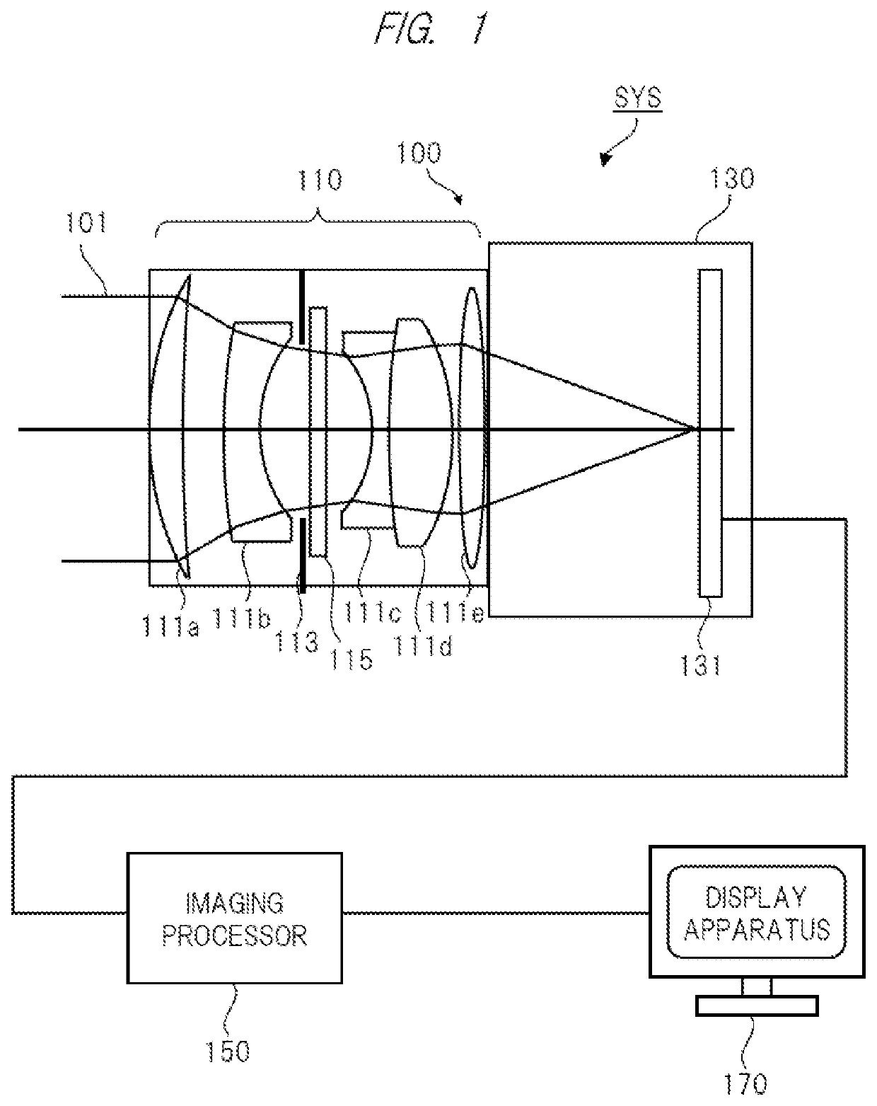
[0025]FIG. 1 is a configurational diagram showing one example of a focal-depth extension optical system including an imaging apparatus according to a first embodiment of the present invention. The focal-depth extension optical system SYS of FIG. 1 is a system that is called, for example, Wavefront Coding (WFC).
[0026]As shown in FIG. 1, the focal-depth extension optical system SYS includes an imaging apparatus 100 and an imaging processor 150. In FIG. 1, note that the configuration of the focal-depth extension optical syste...
first example
[0065]Next, a first example according to the present embodiment will be explained. Each condition of the first example is as follows. An “F” value of the imaging optical system 110 is 2.19, a focal distance of the imaging optical system 110 is 45 mm, a pixel pitch of the imaging sensor 131 is 3.27 μm, the number of pixels of the imaging sensor 131 is 1024×1024, a distance from the imaging apparatus 100 to an image-capturing target object is 18.7 m, the number of annular grooves 116 is three, and the widths of the respective annular grooves 116 are equal to one another.
[0066]FIG. 7 is a diagram exemplifying an additional phase added to the light in the phase plate. FIG. 7 shows the first example, a later-described second example and a related-art example to overlap one another. The related-art example is an example using the configuration of the Patent Document 1. In FIG. 7, a horizontal axis represents a normalized radius at a position at which the optical ray crosses the pupil plan...
second example
[0086]Next, the second example will be explained. As similar to the first example, the second example will be explained with reference to FIGS. 7 to 10. Note that the conditions of the second example are the same as those of the first example except that the number of the annular grooves 116 is four.
[0087]First, FIG. 7 will be explained. In the second example, the longitudinal aberrations Δz of the respective annular grooves 116 are set to be +0.3 mm, −0.3 mm, +0.3 mm and −0.3 mm in an order outward from the inner annular groove. Also in the second example, the function of the wavefront aberration is set for each annular groove 116. As shown in FIG. 7, it is found that the phase distribution is smoothly connected at the boundary between the adjacent annular grooves 116. Therefore, the second example also has the merit that does not generate the scattered light noises or others as similar to the first example.
[0088]Next, FIG. 8 will be explained. As shown in FIG. 8, also in the secon...
PUM
| Property | Measurement | Unit |
|---|---|---|
| area | aaaaa | aaaaa |
| widths | aaaaa | aaaaa |
| radius | aaaaa | aaaaa |
Abstract
Description
Claims
Application Information