Multilayer resin substrate and method of manufacturing multilayer resin substrate

a resin substrate and multi-layer technology, applied in the field of multi-layer resin substrates, can solve the problems of unwanted capacitance formation and change of achieve the effects of reducing or preventing a change in electrical characteristics of the coil, and reducing or preventing a change in unwanted capacitan

Pending Publication Date: 2022-04-28
MURATA MFG CO LTD
View PDF0 Cites 1 Cited by
  • Summary
  • Abstract
  • Description
  • Claims
  • Application Information

AI Technical Summary

Benefits of technology

[0011]According to the manufacturing method described above, even with a configuration including a coil in which a plurality of non-overlapping portions are provided, a multilayer resin substrate capable of significantly reducing or preventing a change in electrical characteristics of the coil due to capacitance to be generated between the non-overlapping portions is able to be easily obtained.
[0012]According to preferred...

Problems solved by technology

However, in a case in which a plurality of coil conductor patterns each including a wide portion are provided and non-overlapping portions of two adjacent wide portions in ...

Method used


Image

  • Multilayer resin substrate and method of manufacturing multilayer resin substrate
  • Multilayer resin substrate and method of manufacturing multilayer resin substrate
  • Multilayer resin substrate and method of manufacturing multilayer resin substrate

Examples


first preferred embodiment

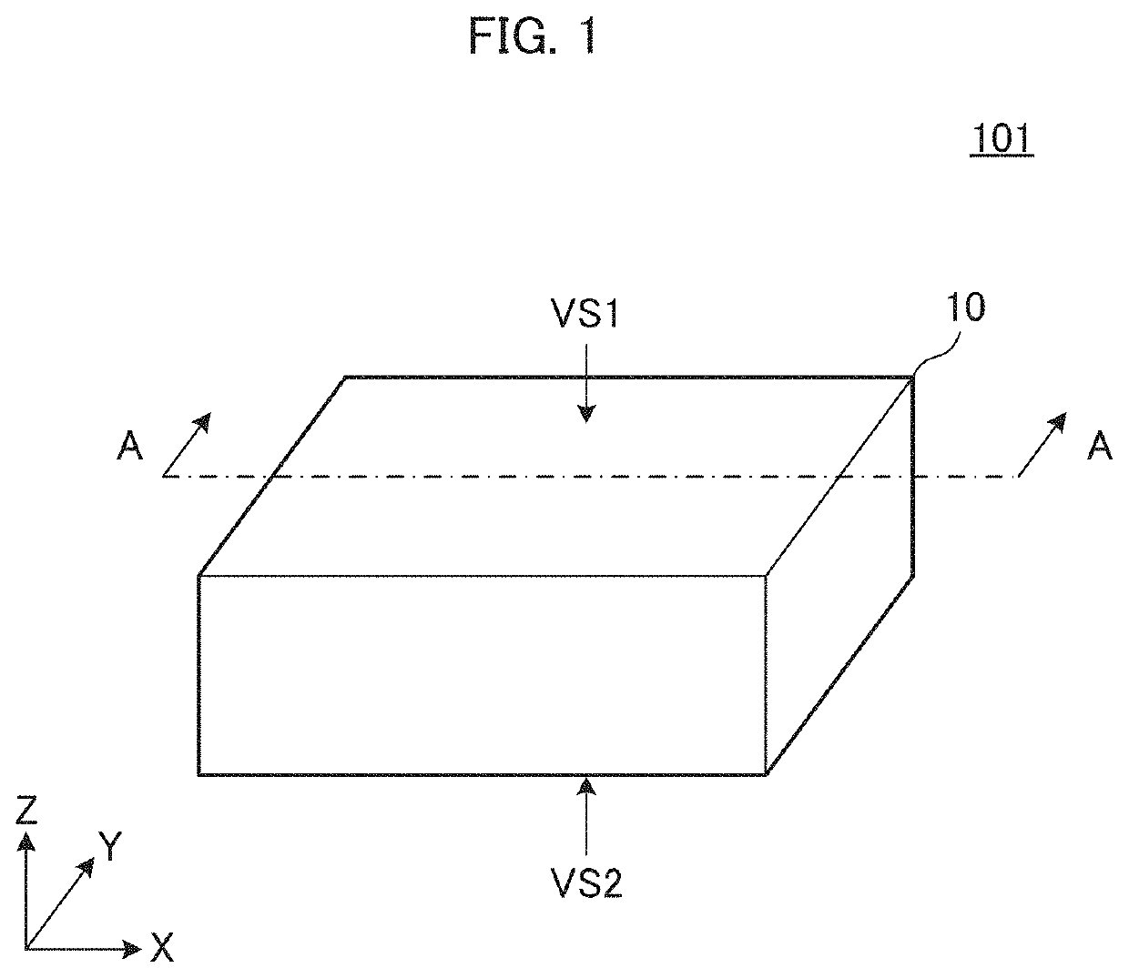
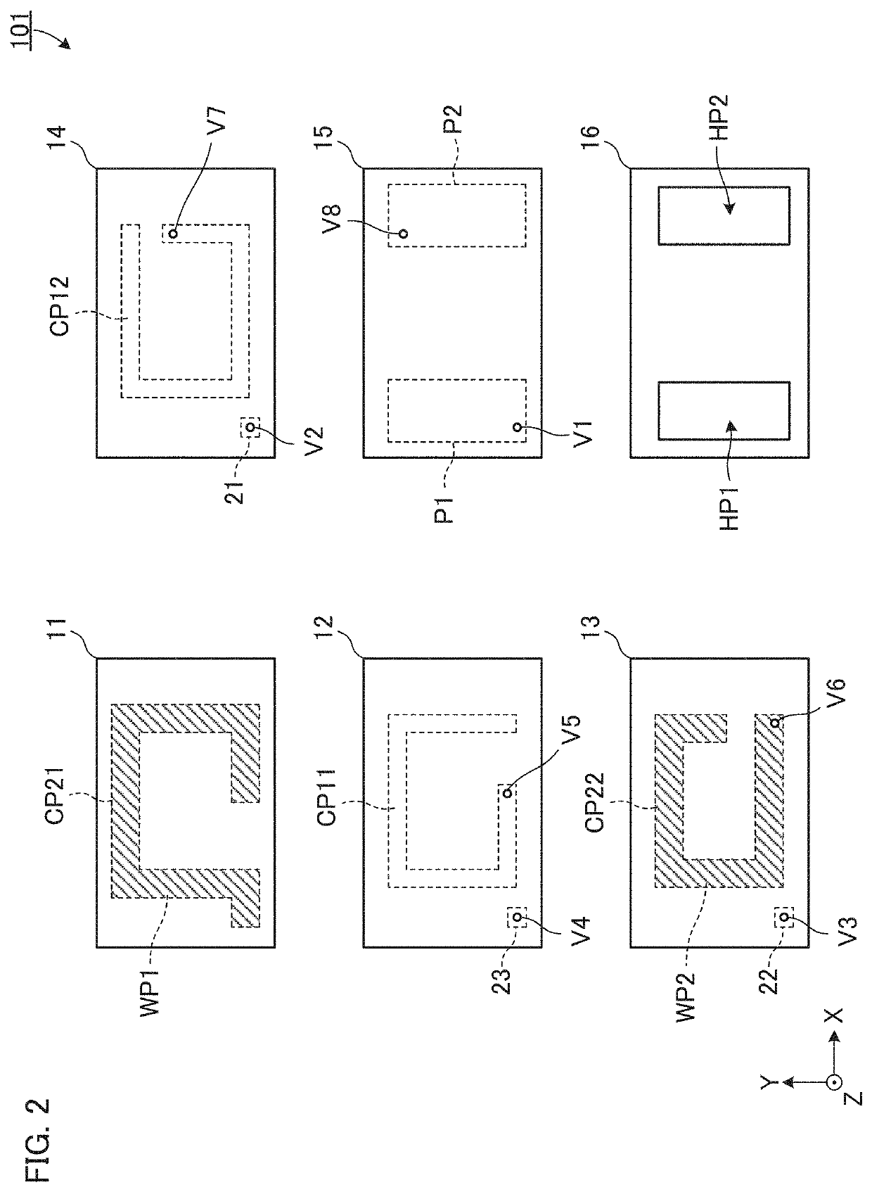
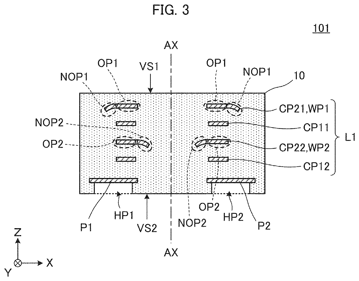
[0032]FIG. 1 is an external perspective view of a multilayer resin substrate 101 according to a first preferred embodiment of the present invention. FIG. 2 is an exploded plan view of the multilayer resin substrate 101. FIG. 3 is an A-A cross-sectional view in FIG. 1. It is to be noted that, in FIG. 2, in order to make the structure easy to understand, wide portions WP1 and WP2 of second coil conductor patterns CP21 and CP22 are indicated by hatching.

[0033]The multilayer resin substrate 101 includes a stacked body 10, a coil L1, and external electrodes P1 and P2. As will be described below, the coil L1 includes a plurality of coil conductor patterns (one or more first coil conductor patterns CP11 and CP12, and two or more second coil conductor patterns CP21 and CP22), and includes a winding axis AX in a Z-axis direction.

[0034]The stacked body 10 has a rectangular or substantially rectangular parallelepiped shape with a longitudinal direction that coincides with an X-axis direction a...

second preferred embodiment

[0093]A second preferred embodiment of the present invention shows an example of a multilayer resin substrate in which a coil (a plurality of coil conductor patterns) does not overlap with an external electrode, when viewed in a stacking direction.

[0094]FIG. 7 is an external perspective view of a multilayer resin substrate 102 according to the second preferred embodiment of the present invention. FIG. 8 is an exploded plan view of the multilayer resin substrate 102. FIG. 9 is a B-B cross-sectional view in FIG. 7. In FIG. 9, in order to make the structure easy to understand, wide portions WP1 and WP2 of second coil conductor patterns CP21A and CP22A are indicated by hatching.

[0095]The multilayer resin substrate 102 includes a stacked body 10A, a coil L2, and external electrodes P1A and P2A. The stacked body 10A has a longer length in the longitudinal direction (the X-axis direction) than the stacked body 10 described in the first preferred embodiment. Other configurations of the stac...

third preferred embodiment

[0119]A third preferred embodiment of the present invention shows an example of a multilayer resin substrate including a plurality of spiral-shaped coil conductor patterns.

[0120]FIG. 11 is an external perspective view of a multilayer resin substrate 103 according to the third preferred embodiment of the present invention. FIG. 12 is an exploded plan view of the multilayer resin substrate 103. FIG. 13 is a C-C cross-sectional view in FIG. 11. In FIG. 12, in order to make the structure easy to understand, wide portions WP1 and WP2 of second coil conductor patterns CP21B and CP22B are indicated by hatching.

[0121]The multilayer resin substrate 103 is different from the multilayer resin substrate 102 according to the second preferred embodiment in that a coil L3 is provided. The coil L3 includes a plurality of coil conductor patterns (one or more first coil conductor patterns CP11B and CP12B, and two or more second coil conductor patterns CP21B and CP22B). Other configurations of the mul...


PUM


Abstract

A multilayer resin substrate includes a stacked body, and a coil including a first coil conductor pattern and a second coil conductor pattern. The second coil conductor pattern includes a wide portion with a line width larger than a line width of the first coil conductor pattern. The wide portion includes overlapping portions that overlap with the first coil conductor pattern, and non-overlapping portions that do not overlap with the first coil conductor pattern, when viewed in a Z-axis direction. Adjacent non-overlapping portions in the Z-axis direction, when viewed in the Z-axis direction, protrude in opposite directions to each other in a radial direction, with respect to the first coil conductor pattern.

Description

CROSS REFERENCE TO RELATED APPLICATIONS[0001]This application claims the benefit of priority to Japanese Patent Application No. 2019-133245 filed on Jul. 19, 2019 and is a Continuation Application of PCT Application No. PCT / JP2020 / 027688 filed on Jul. 16, 2020. The entire contents of each application are hereby incorporated herein by reference.BACKGROUND OF THE INVENTION1. Field of the Invention[0002]The present invention relates to a multilayer resin substrate in which a plurality of resin layers each include a coil conductor pattern, and relates to a method of manufacturing such a multilayer resin substrate.2. Description of the Related Art[0003]Conventionally, a multilayer resin substrate including a stacked body provided by stacking a plurality of resin layers, and a coil configured to include a plurality of coil conductor patterns provided in the stacked body and including a winding axis in a stacking direction, has been known.[0004]For example, International Publication No. 20...

Claims


Application Information

Patent Timeline
IPC IPC(8): H01F27/28H01F27/29H01F27/32H01F41/04H01F41/12
CPCH01F27/2804H01F27/29H01F27/323H01F27/2871H01F41/122H01F2027/2809H01F41/042H05K1/16H05K3/46H01F5/003H01F41/041
Inventor SUGI, RINTAROARAKI, KEISUKE
Owner MURATA MFG CO LTD
Why Eureka
Try Eureka