
Method, computer program and apparatus for analysing a programmable logic controller program

a programmable logic controller and program technology, applied in the direction of electrical programme control, program control, instruments, etc., can solve the problems of inability to guarantee that the selected tests cover all, inability to exhaustively and exhaustively solve the problem of factory bugs, and inability to guarantee the accuracy of the selected tests

Pending Publication Date: 2022-05-05
MITSUBISHI ELECTRIC CORP
View PDF0 Cites 1 Cited by
  • Summary
  • Abstract
  • Description
  • Claims
  • Application Information

AI Technical Summary

Benefits of technology

The patent describes a method for automatically debugging computer programs by detecting and explaining errors during execution. The method can detect both instruction errors and functional specifications violations, and can print additional information about memory values during execution. The method allows for automatic debugging without the need for human intervention. The method also includes a step of translating the original program into a model to keep track of internal memory values during execution. The technical effect of this invention is improved efficiency and accuracy in identifying and fixing errors in computer programs.

Problems solved by technology

Debugging needs to be performed before implementation in production environment, since bugs in factories can be extremely expensive in terms of human and material damages, and plant closing time.
The main drawback of such a method is that it is not exhaustive and is time-consuming and therefore costly.
This non-exhaustivity makes it quite impossible to guarantee that the selected tests cover all possible executions of a program once in production environment.
However, execution paths-related complexity is often exponential especially for industrial applications.
Testing efficiency is limited by CPU time and, therefore, this method is still not exhaustive.
Although part of tests generation and execution can be automated, another drawback of such a method is that output values of the test still must be analysed by programmers, the only available information about the bug being the initial configurations of inputs and internal memory that lead to the bug.
It is therefore often hard to understand the fundamental reason of the error and why the considered initial configuration leads to that error at some point of the program.

Method used


Image

  • Method, computer program and apparatus for analysing a programmable logic controller program
  • Method, computer program and apparatus for analysing a programmable logic controller program
  • Method, computer program and apparatus for analysing a programmable logic controller program

Examples


Embodiment Construction

[0045]In the figures, the same references denote identical or similar elements.

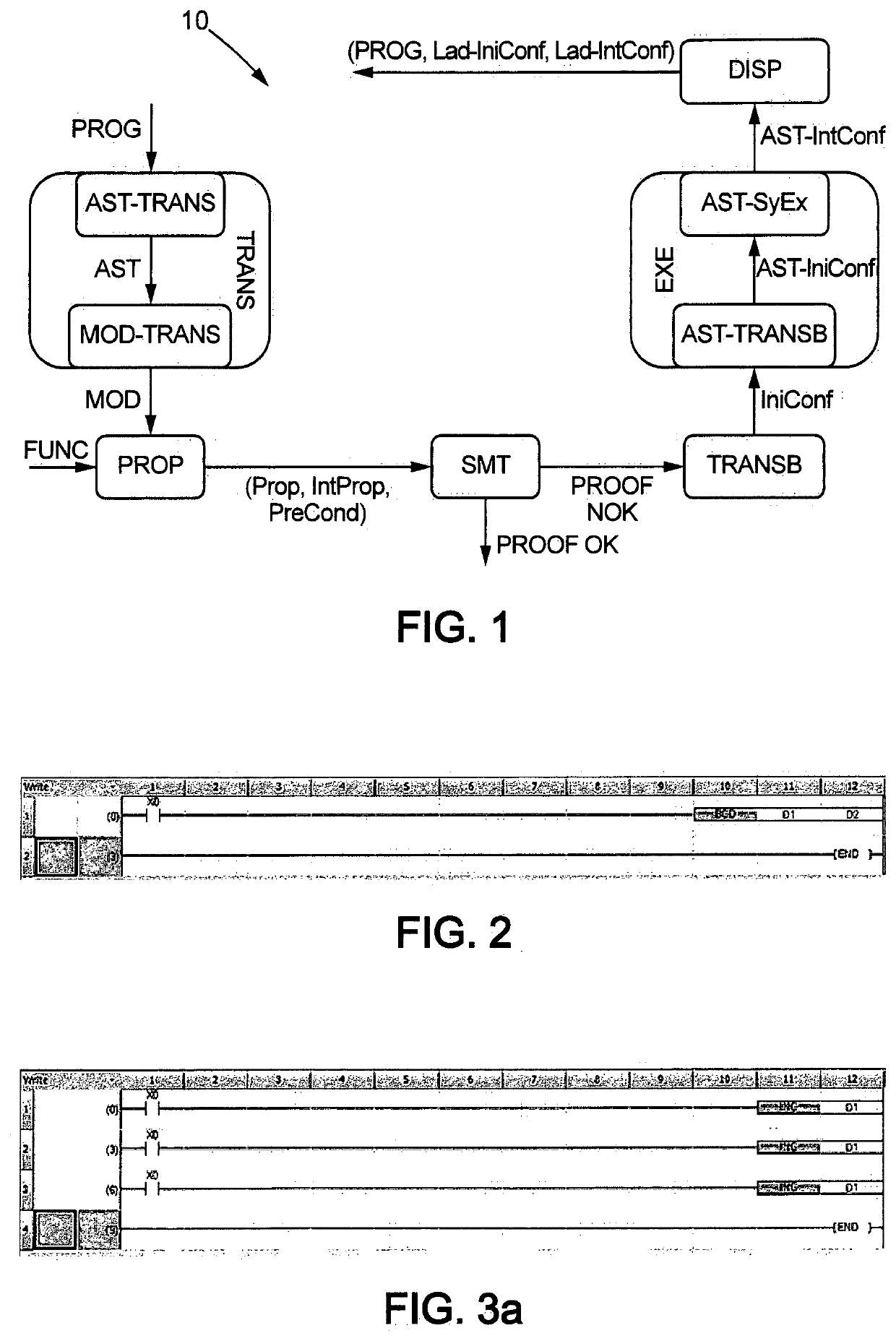
[0046]FIG. 1 shows an exemplary set of steps designated by reference numeral 10 and involved in a Ladder program deductive verification.

[0047]The first step (TRANS) of the method is a translation step, consisting in translating a PLC program (PROG) into a model (MOD).

[0048]Said PLC program PROG is executable on a programmable logic controller hereinafter referred to as PLC. A PLC is capable of storing and executing instructions, such as sequencing, timing, counting, arithmetic, data manipulation, and communication, in order to control industrial machines and processes. Interfacing circuitry to field devices is provided in the form of input and output connections.

[0049]A Ladder diagram represents the sequential control logic of the PLC program in a graphical diagram. The Ladder language is a graphical language which mimics a relay logic electrical schematic as shown in FIG. 2 which represents an example of...


PUM


Abstract

It is disclosed a PLC Program analysis method where a program (PROG) is translated (TRANS) into a model (MOD) in a logical framework, from which properties (Prop) are determined. Said properties coupled with user specifications (IntProp) are verified by an automated solver (SMT). If contraposition of a property (Prop) is satisfiable, counter-examples (PROOF NOK) representative of model inputs and internal memory values is provided. Counter-examples (PROOF NOK) are translated into error initial configurations (IniConf) of said model. Execution of the model is simulated (EXE) with said model error initial configurations (IniConf), and error intermediary configurations (AST-IntConf) of said model simulation are recorded up to said property violation. Error initial and intermediary configurations (Lad-IniConf, Lad-IntConf) of said original program (PROG) are derived from error initial configurations (IniConf) of said model and error intermediary configurations (AST-IntConf) of said model simulation and displayed. An apparatus for executing said method is provided.

Description

TECHNICAL FIELD[0001]The present invention relates to methods and apparatuses for analysing a program written in a language described in the IEC 61113-3 standard. Such a program is intended in particular for a Programmable Logic Controller (PLC) to carry out the control of industrial systems.[0002]The present invention relates more particularly to a method and apparatus for analysing, detecting and correcting errors in a Ladder program.BACKGROUND ART[0003]Programmable logic controllers (PLC) are industrial digital computers used as automation controllers of manufacturing processes, such as assembly lines or robotic devices.[0004]PLCs are provided with software that computes outputs from the values of inputs and internal memory, and have therefore replaced hard-wired relays, timers and sequencers. Ladder language, also known as Ladder Logic, is a programming language used to develop PLCs software. This language uses circuits' diagrams of relay logic hardware to represent a PLC progra...

Claims


Application Information

Patent Timeline
IPC IPC(8): G05B19/05
CPCG05B19/056G05B2219/13004G05B19/0426G05B2219/13052G05B2219/13142
Inventor COUSINEAU, DENIS
Owner MITSUBISHI ELECTRIC CORP
Learn More