
Automated tomography field ion microscope

a tomography and ion microscope technology, applied in the field of automatic tomography field ion microscope, can solve the problems of difficult control of optimal imaging parameters, small use, and difficulty in effectively identifying objects of interest during the course of analysis

Pending Publication Date: 2022-05-05
CENT NAT DE LA RECHERCHE SCI +2
View PDF1 Cites 0 Cited by
  • Summary
  • Abstract
  • Description
  • Claims
  • Application Information

AI Technical Summary

Benefits of technology

The invention proposes a method to image materials to atomic scale using a field-ion microscope. The method allows for obtaining high-quality images of each atom throughout the erosion of the tip. This improves the accuracy and efficiency of the imaging process.

Problems solved by technology

This instrument exhibits good performance levels for observing structural material defects, but it remains little used.
Its main drawback is the difficulty in controlling the optimal imaging parameters during the acquisition of thousands of images of a material.
It is then difficult to effectively identify the objects of interest during the course of the analysis.
Therefore the quality of the images of the surface atoms degrades over time.
Furthermore, depending on the pulsed potential value applied, either too few atoms evaporate, and in this case, the analysis of the internal structure of the material risks being very costly in time; or a great number of atoms evaporate from the tip, and in this case, it is difficult to know if only one atomic plane has evaporated or if several planes have evaporated.
However, the atoms are not all visible on the images with the same resolution, since the potential applied is not always the best image potential, but a potential of uncontrolled value, which makes the tracking of certain atoms difficult.

Method used


Image

  • Automated tomography field ion microscope
  • Automated tomography field ion microscope

Examples


Embodiment Construction

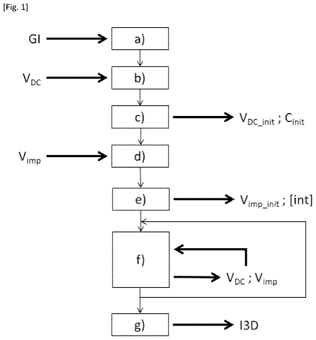
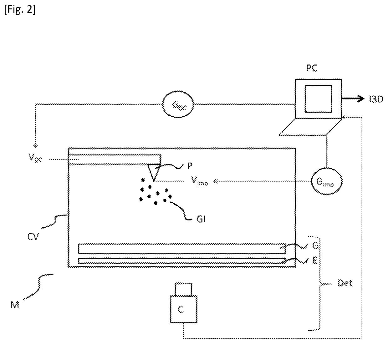
[0039]The first step of the method (step a)) consists in introducing an imaging gas GI into the vacuum chamber of the microscope. This imaging gas GI is at low pressure in the vacuum chamber and can be chosen from among neon, helium, hydrogen, argon or another gas at a pressure lower than 0.1 Pa (10-4 mbar).

[0040]In the second step of the method (step b)), a DC electrical potential VDC is applied to the tip so as to create an electrical potential difference with respect to the walls of the vacuum chamber. This potential difference has the effect of provoking the ionization of the imaging gas GI above the atoms of the surface of the tip. Again by potential difference effect, the ions thus formed by the image gas GI will be repelled from the surface of the tip and migrate toward the ion detector.

[0041]In step c), ion images of the impacts of the ions, deriving from the ionization of the imaging gas GI and repelled by the tip onto the detector for different DC electrical potential VDC ...


PUM


Abstract

A method for imaging a material to atomic scale by means of a field-ion microscope having a vacuum chamber configured to accommodate the material prepared in the form of a tip and an imaging gas, and an ion detector is provided. The method includes application of a DC electrical potential (VDC) and of a pulsed electrical potential, of which the maximum pulse value is denoted Vimp, so that the tip erodes for a potential value equal to VDC+Vimp; acquisition, by the detector between at least two pulses of the pulsed potential, of series of at least two ion images of the impacts of the ions repelled by the tip onto the detector; and calculation of a quantity characteristic of a trend of the erosion of the tip based on the series of ion images acquired and the adjustment, between each series of images, of the values of VDC and of Vimp such that the quantity characteristic of the trend and the ratio VDC / Vimp remain constant.

Description

CROSS-REFERENCE TO RELATED APPLICATIONS[0001]This application is a national phase entry of PCT / EP2020 / 054508, filed on Feb. 20, 2020, which claims the benefit of priority of French Patent Application No. 1902139, filed on Mar. 1, 2019, the contents of which being hereby incorporated by reference in their entirety for all purposes.FIELD[0002]The present invention relates to a method for imaging a material to atomic scale and a field-ion microscope.BACKGROUND[0003]The field-ion microscope is an instrument that was invented in the 1950s. This instrument exhibits good performance levels for observing structural material defects, but it remains little used. Its main drawback is the difficulty in controlling the optimal imaging parameters during the acquisition of thousands of images of a material. It is then difficult to effectively identify the objects of interest during the course of the analysis. The variation of the quality of the images notably prevents an extraction and a correct r...

Claims


Application Information

Patent Timeline
IPC IPC(8): H01J37/26H01J37/285
CPCH01J37/265H01J2237/2852H01J2237/2626H01J37/285
Inventor VURPILLOT, FRANÇOISLARDE, RODRIGUEKLAES, BENJAMINDA COSTA, GÉRALD
Owner CENT NAT DE LA RECHERCHE SCI
Learn More