
Vaporizing apparatus for thin film deposition

a technology of vaporizing apparatus and thin film, which is applied in the direction of evaporation, separation processes, coatings, etc., can solve the problems of deterioration in valorization efficiency, inevitably complicated or enlarged configuration of vaporizing apparatus, and decrement in life span. , to achieve the effect of improving vaporization efficiency

Pending Publication Date: 2022-05-12
MI
View PDF9 Cites 0 Cited by
  • Summary
  • Abstract
  • Description
  • Claims
  • Application Information

AI Technical Summary

Benefits of technology

This patent describes a vaporizing apparatus for thin film deposition in semiconductor fabrication that improves vaporization efficiency by preventing recondensation of sprayed droplets and allowing them to collide with a heater for atomization and vaporization.

Problems solved by technology

However, when the efficiency in vaporization of a liquid source into a gaseous source is low, a non-vaporized source may be adhered to an inner wall of a vaporizing apparatus or a filter, and thus the life span may be degraded and device failure may be caused.
However, the decompressing vaporization method may vaporize only a portion of the liquid source, and thus the deterioration in the valorization efficiency still exists.
Accordingly, to vaporize the liquid source entirely or vaporize the liquid source over a desired amount, a configuration of a vaporizing apparatus is inevitably complicated or enlarged.
Due to the complication or enlargement of the vaporizing apparatus, the source vaporized in the vaporizing apparatus may be liquefied again while the vaporized source flows in a complicate passage in the vaporizing apparatus.
Further, to vaporize a large amount of liquid source, the vaporizing apparatus may be more complicated and enlarged, and thus the above-described problems may be more aggravated, the design of the vaporizing apparatus is more complicated, and the manufacturing cost is increased.

Method used


Image

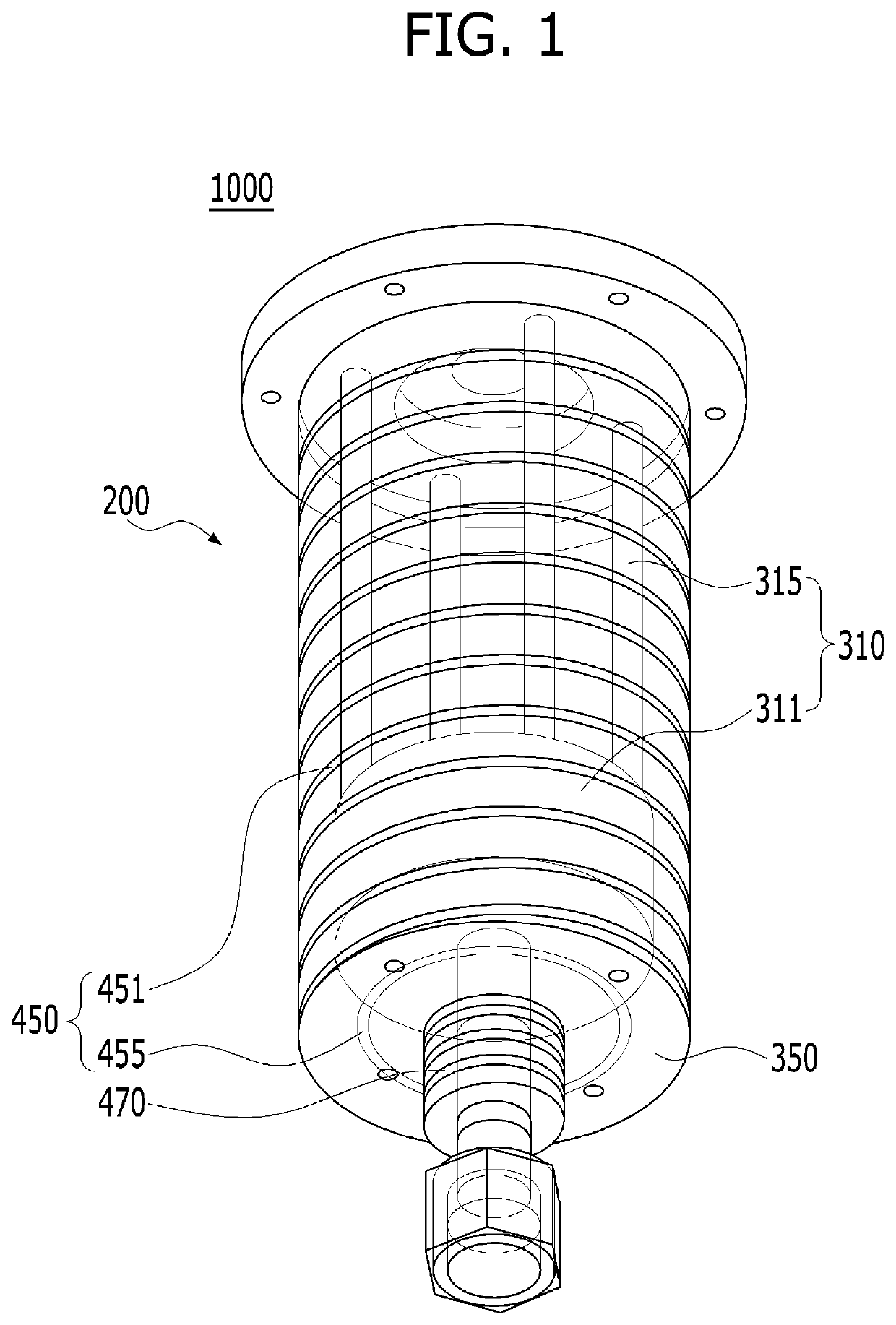
  • Vaporizing apparatus for thin film deposition
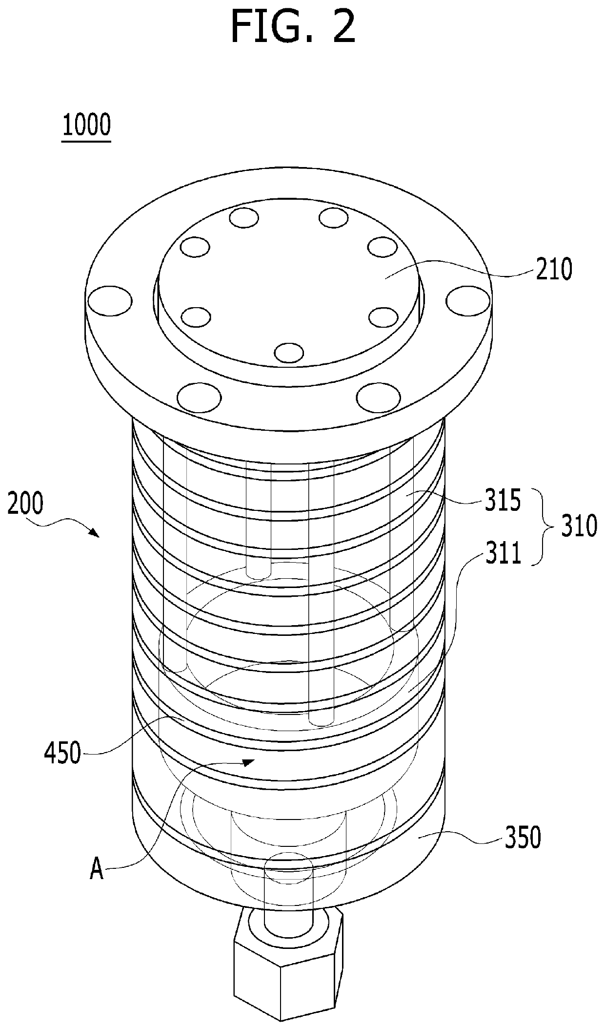
  • Vaporizing apparatus for thin film deposition
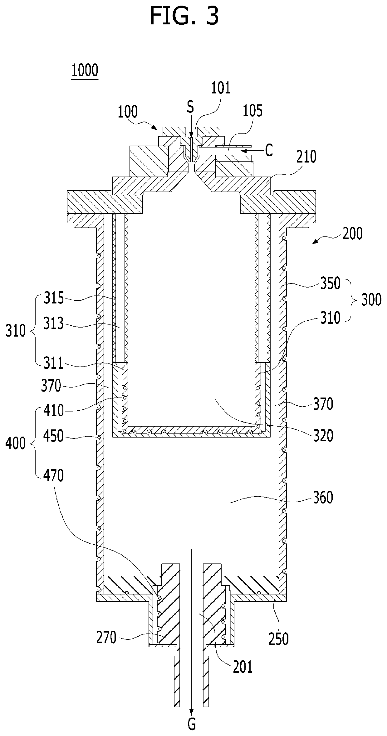
  • Vaporizing apparatus for thin film deposition

Examples


Embodiment Construction

[0036]Hereinafter, exemplary embodiments of the disclosure will be described more fully with reference to the accompanying drawings, in which the exemplary embodiments of the disclosure are shown to understand a configuration and an effect of the disclosure. However, specific structural and functional details disclosed herein are merely representative for purposes of describing exemplary embodiments. Thus, the invention may be embodied in many alternate forms and should not be construed as limited to only exemplary embodiments set forth herein.

[0037]Accordingly, while example embodiments are capable of various modifications and alternative forms, embodiments thereof are shown by way of example in the drawings and will herein be described in detail. It should be understood, however, that there is no intent to limit example embodiments to the particular forms disclosed, but on the contrary, example embodiments are to cover all modifications, equivalents, and alternatives falling withi...


PUM

PropertyMeasurementUnit
vaporization areaaaaaaaaaaa
temperatureaaaaaaaaaa
fixed temperatureaaaaaaaaaa

Abstract

A vaporizing apparatus for thin film deposition is provided. The vaporizing apparatus includes an atomizer configured to mix a source injected through a source inlet and a carrier gas injected through a carrier gas inlet and spray a mixed gas, a vaporizing unit including a first vaporization area and a second vaporization area, which are configured to vaporize the mixed gas sprayed from the atomizer, and configured to discharge a vaporized gas as a process gas through an outlet, and a heating unit configured to maintain the mixed gas in the vaporizing unit at a fixed temperature. The heating unit includes a first heating part arranged to surround the first vaporization area and configured to maintain the temperature of the mixed gas in the first vaporization area and a second heating part arranged to enclose the second vaporization area with the first heating part and configured to maintain the temperature of the mixed gas in the second vaporizing space.

Description

BACKGROUND OF THE INVENTIONField of the Invention[0001]Various embodiments may generally relate to a vaporizing apparatus for thin film deposition, and more particularly to a vaporizing apparatus with high vaporization efficiency, which is used to deposit a thin film in semiconductor fabrication and is capable of preventing recondensation of sprayed droplets through an improved heater structure.Description of the Related Art[0002]In general, semiconductor devices, display devices, and the like are manufactured through a series of processes such as a thin film deposition process and a photolithography process using a semiconductor manufacturing apparatus. Among the series of processes, the thin film deposition process for forming a thin film on a substrate may be performed through a chemical vapor deposition (CVD) method or an atomic layer deposition (ALD) method.[0003]Typically, the thin film deposition process may be a process which forms a thin film on a substrate (wafer) by injec...

Claims


Application Information

Patent Timeline
Patent Type & Authority Applications(United States)
IPC IPC(8): C23C16/448B01B1/00
CPCC23C16/4486B01B1/005C23C16/4481H01L21/67017H01L21/67103B01D1/14B01D1/16B01D1/22H01L21/67011
Inventor KIM, GI NAM
Owner MI
Learn More