
Test system configuration adapter systems and methods

a technology of adapter system and test system, applied in the field of electronic testing, can solve the problems of complex devices under test (duts), difficult to achieve the effect of standardized testing procedures, and high cost of traditional methods

Pending Publication Date: 2022-05-19
ADVANTEST CORP
View PDF10 Cites 0 Cited by
  • Summary
  • Abstract
  • Description
  • Claims
  • Application Information

AI Technical Summary

Benefits of technology

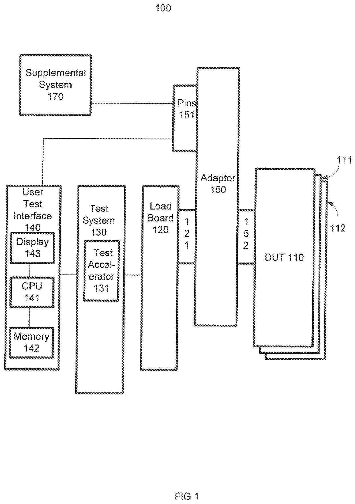
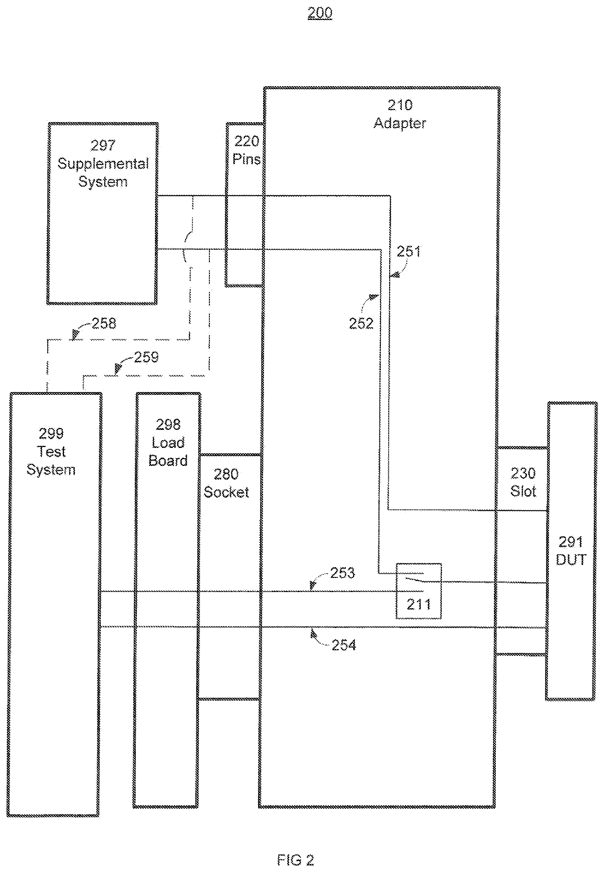
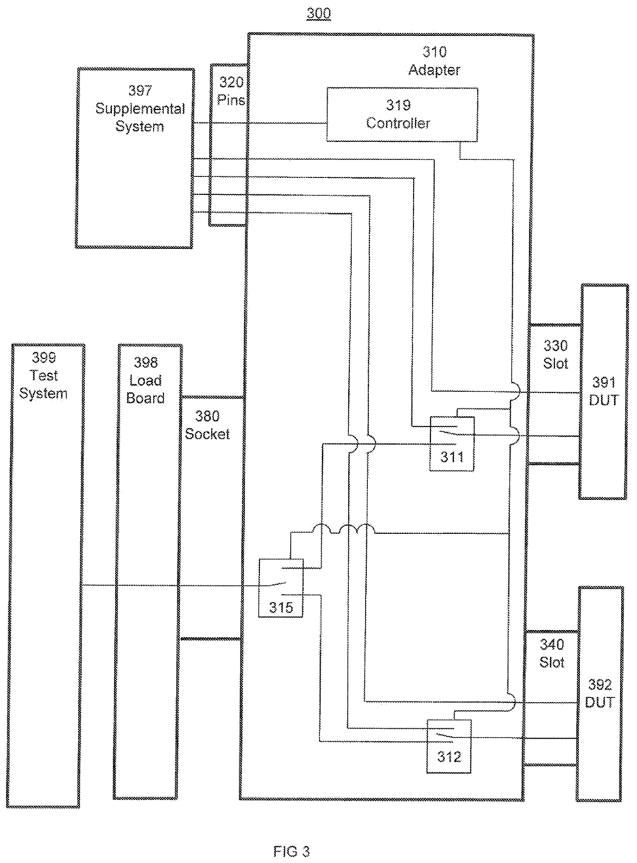
This patent describes a test system that allows for flexible and efficient testing of different types of procedures. The test system includes a configuration adapter with a tester side socket, break out pin, and a device under test side slot. The adapter enables communication between the device under test and the test equipment as well as supplemental equipment, while keeping the device under test connected to the test system. The breakout pin and tester side socket can be selectively coupled to the device under test side slot, and a controller can direct the selection of coupling between the supplemental operations and the functional testing for the device under test. The supplemental operations can include scan testing, and the supplemental equipment can be included in the test equipment. This system allows for efficient and flexible testing of different procedures on various devices.

Problems solved by technology

While testing of the systems and devices has made significant advances, traditional approaches are typically expensive and often have limitations with regards to throughput and convenience.
Devices under test (DUTs) are often complex and require different types of complicated testing procedures to achieve reliable results.
A lot of testing related costs are incurred in the loading / unloading of DUTs into the separate supplemental equipment and functional testers.
This process can be labor intensive and cumbersome.
Conventional systems are not typically efficient with respect to multiple different types of testing and supplemental operations because: 1) the separate different systems are expensive to build and operate; and 2) physical manipulation (e.g., insertion, removal, etc.) of the devices under test between the separate test systems is labor intensive.
The amount of work is considerable because the loadboards typically need to be manually removed from the environmental chamber and changed, manually populated with the numerous devices under test, and then manually recoupled to the tester slice.
The conventional test head and oven enclosure access restrictions and typical hardwired nature of the test slice and loadboard coupling all add to the difficulty of the task.
Other aspects of conventional test approaches also often adversely impact productivity and throughput.
These cumbersome conventional device under test approaches usually interrupt testing operations of all the devices under test and do not typically allow flexible or continued testing of some devices while other devices are physically manipulated.
There is a long felt need for a less expensive and convenient production electronic device testing and supplemental operation approach due to costs and difficulties associated traditional approaches to performing different types of testing (e.g., supplemental operations, functional testing, performance testing, etc.).

Method used


Image

  • Test system configuration adapter systems and methods
  • Test system configuration adapter systems and methods
  • Test system configuration adapter systems and methods

Examples


Embodiment Construction

[0021]Reference will now be made in detail to the preferred embodiments of the invention, examples of which are illustrated in the accompanying drawings. While the invention will be described in conjunction with the preferred embodiments, it will be understood that they are not intended to limit the invention to these embodiments. On the contrary, the invention is intended to cover alternatives, modifications and equivalents, which may be included within the spirit and scope of the invention as defined by the appended claims. Furthermore, in the following detailed description of the present invention, numerous specific details are set forth in order to provide a thorough understanding of the present invention. However, it will be obvious to one ordinarily skilled in the art that the present invention may be practiced without these specific details. In other instances, well known methods, procedures, components, and circuits have not been described in detail as not to unnecessarily o...


PUM


Abstract

Presented embodiments facilitate efficient and effective flexible implementation of different types of testing procedures in a test system. In one embodiment, a test system configuration adapter includes a tester side socket, a break out pin, and a device under test side slot. The tester side socket is configured to couple with a test equipment socket. The break out pin is configured to couple with the supplemental equipment. The device under test side slot is configured to couple with the tester side socket, the break out pin, and a device under test, wherein the tester side socket. The test system configuration adapter is configured to enable communication between test equipment coupled to the test equipment socket and supplemental equipment coupled to the breakout pin while the device under test remains coupled to the device under test side slot. In one exemplary implementation, the breakout pin and tester side socket are selectively coupled to the device under test side slot. The test system configuration adapter can include a switch configured to switch a portion of the coupling of the device under test side slot to the tester side socket and the break out pin.

Description

FIELD OF THE INVENTION[0001]The present invention relates to the field of electronic testing.BACKGROUND OF THE INVENTION[0002]Electronic systems and devices have made a significant contribution towards the advancement of modern society and have facilitated increased productivity and reduced costs in analyzing and communicating information in a variety of business, science, education, and entertainment applications. These electronic systems and devices are typically tested to ensure proper operation. While testing of the systems and devices has made significant advances, traditional approaches are typically expensive and often have limitations with regards to throughput and convenience.[0003]Devices under test (DUTs) are often complex and require different types of complicated testing procedures to achieve reliable results. Usually, testing is directed to determining if a device under test is performing and functioning properly. In addition, many other types of supplemental operation...

Claims


Application Information

Patent Timeline
Patent Type & Authority Applications(United States)
IPC IPC(8): G01R1/04G01R31/319G01R31/3185
CPCG01R1/0441G01R31/318519G01R31/31905G01R31/00G01R1/0408G01R31/2889
Inventor CHOW, EDDY WAYNE
Owner ADVANTEST CORP
Learn More